Operational efficiency saves $7.3 maillion on eight-well sidetrack program in Gulf of Mexico
Chevron USA Production Co., operator for the Main Pass 299 and 144 fields offshore Loui siana, planned and drilled an eight-well sidetrack program, including a horizontal completion in record time and saving $7.3 million over similar historical offsets.
Based on a benchmarking effort, the drilling team made changes to the bottomhole assembly and adjustable kick-off tool settings. The team also chose steerable ream-while-drilling (SRWD) systems with roller cone bits and used synthetic mud systems.
The eccentric SRWD technology allowed the operator successfully to drill the oversize boreholes required and reach directional targets in record time, eliminating costly underreamer runs. The oversized boreholes allowed casing to be run to bottom without incident, ensuring good cement bonding with the pipe every time.
The resulting operational efficiencies allowed the drilling team to achieve bottomhole objectives quickly, reducing reservoir formation exposure time to drilling fluids and also reducing costly "flat," nonproductive rig time. The operator achieved significant savings from reduced completion costs.
Drilling operations were incident free. No accidents, spills, or noncompliance issues occurred during the program.
Main Pass 299 and144
Main Pass 299 and 144 fields are about 100 miles southeast of New Orleans in the Gulf of Mexico in about 225 ft of water.
The overburden is mostly soft, unconsolidated shales (gumbo) and the reservoir consists of Miocene sands. Production in the area is controlled by a large salt dome that stratigraphically traps oil reserves.
The first wells were drilled as early as 1962, and first commercial production began in 1967. The operator's current focus is on reentry projects to enhance production in the field.
Jack up rigs cantilevered over the production platforms drilled most of the wells, which produce through 23/8 or 27/8-in. tubing, inside 7 or 75/8-in. casing. The producing sands range from 4,000 to 10,000 ft true vertical depth.
The drilling team performed well reentry completions by milling out of the existing casing. The recompletion hole angles varied and were either vertical, 20°, or horizontal.
The operator used two jack up rigs, drilling simultaneously to complete the wells in about 67 days, for both the drilling and completion phases of the project.
Benchmarking
One of the most important aspects of improving drilling performance in the area was to document achievements as well as failures and then objectively benchmark the data against the best in class for the area.
The drilling team began analyzing offset drilling data in the Gulf of Mexico in mid-1999 to compare with the performance in Main Pass 299.
It became necessary to use an algorithm impartially to compare one operation type with another, since complexity varies significantly from well to well.
As a solution, the operator applied a proprietary mechanical risk index (MRI). Mathematical evaluation of the MRI considers various well and drilling parameters:
- Water depth.
- Measured depth.
- True vertical depth.
- Kickoff point (for sidetracks).
- Mud weight.
- Horizontal displacement.
- Number of casing strings.
- "S" shaped well path.
- H2S or CO2 environment.
- Presence of hydrates.
- Depleted sands with differential pressure greater than 3,000 psi.
- Subsea wellhead or mudline suspension system.
- Penetration of salt formations.
- Borehole size less than 61/2 in.
- Horizontal borehole.
Although not 100% accurate, the MRI method standardizes well complexities for the purpose of benchmarking.
Prior to 1999, sidetracking operations in MP 299 were hampered primarily by low penetration rate, numerous bit trips, and poor hole conditions.
Although MP 299 had several good drilling prospects in the range of 200,000-400,000 boe gas, they were considered uneconomical relative to the costs of drilling new wells. The prospects were even uneconomical relative to historical and conventional sidetracking efforts.
To capitalize on these opportunities, the operator's management implemented a new philosophy stressing operational excellence and urgency to change from past, accepted practices. The approach held individuals accountable for team performance and was the driver to achieving new efficiencies.
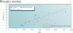
To illustrate historical sidetrack drilling performance in Main Pass 299, the team plotted MRI against days from spud date to TD for 1993-1998 (Fig. 1).
After completion of the initial benchmarking process, further analysis revealed that only one sixth of the data contained MRI calculations, and the authors questioned if the graph truly represented drilling performance in the best-in-class area.
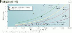
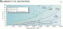
After additional statistical analysis, the drilling team developed another set of curves showing historical sidetrack performance in the Main Pass 299 and144 fields, also for the same period 1993-98, plotted as drilling days vs. TD (Fig. 2).
The curves present data available in the public record but do not differentiate between sidetracks and new drills. The data are divided into first through fourth quartile, in terms of performance.
Planning
The drilling team used the MRI and TD vs. drilling days plots to identify the two most efficient drilling operations (Figs. 1 and 2). The team analyzed why the wells were efficient and adopted some of the best drilling practices from the two wells for use in the eight-well program.
The eight wells planned in Main Pass 299 and144 were to be drilled out of the 7 or 75/8-in. casing.
Since completion requirements called for 5 or 51/2-in. casing liners, oversized boreholes were required to ensure the casing liners would reach bottom when they were run. Also oversized holes were required to ensure effective cement jobs.
The directional objectives of the program ranged from straightforward sidetracks to a horizontal application requiring 8°/100 ft build rate.
Because of bicenter bit geometry, bottomhole assemblies require high torque, "true slick," positive-displacement motors.
In the case of 43/4 in. positive-displacement motors, "true slick" refers to the bearing housing section. This must be 43/4 in. OD, as opposed to 51/8 in. OD of the slick sleeve, which normally covers the bearing housing when lower stabilization is not required.
The directional objective of each well and the required pass-through borehole diameter controls the upper stabilizer gauge.
In general, bottomhole assemblies are run with adjustable kick off, motor bend settings at double the angle that is normally required for an assembly with conventional bit and top stabilizer, 1/8 to 3/4-in. undergauge of the pass-through diameter for build assemblies and close to or at pass-through diameter for drop assemblies.
Throughout the program, the bottomhole assemblies were fine-tuned for maximum drilling efficiency. From a directional standpoint, one significant aspect the drilling team had to consider was drill bit selection to drill the oversize hole.
Conventional one-piece bicenter bits have a polycrystaline diamond (PDC) pilot bit that can cause orientation problems, particularly with an aggressive cutting structure.1 For this reason, the team used a two-piece steerable ream-while-drilling tool. A steel-tooth pilot bit could be run with the SRWD tool, improving steerability and penetration rates.
The drilling team made another preprogram decision to use synthetic drilling fluid, primarily to reduce friction and impede reactive clays swelling. Reducing friction also reduces torque and drag and dramatically improves steerability with the bicenter bit configuration.
The drilling team felt that all of these factors would reduce bit balling and allow for a smoother wellbore to be drilled, optimizing penetration rate and ultimately facilitating trouble free-completion operations.
Ream while drilling
Two-piece, ream-while-drilling tools (RWD) enable operators simultaneously to drill and ream an interval. This eliminates additional underreamer runs with potential tool failures (loss of underreamer arms) and additional drilling time.
Operators have cut costs worldwide by extensively using ream-while-drilling technology.2-6 Historically, wells drilled with conventional bicenter bits have been at the lower end of the cost curve.
Recently, the ability to drill and ream in a single pass has become even more advantageous as directional and horizontal wells can be drilled with steerable ream-while-drilling tools in conjunction with steerable motors.7-9
The RWD differs from conventional bicenter bits in two ways. They feature two-piece design, allowing flexibility in pilot bit selection (Fig. 3). Also, pilot stabilization pads are used to balance the forces acting on the reamer.
The first section of the RWD system is the pilot bit. The second section is a tube incorporating the reamer blades and PDC cutters.
This design minimizes vibration and provides a smooth open hole with a more consistent diameter than drilled with a standard bicenter bit (Figs. 4a and 4b).
The ream-while-drilling system geometry revolves around three interrelated diameters: pass-through, drill size, and pilot bit diameter.
Pass-through is the drift diameter of the casing or liner that the system must go through. Drill size is the final borehole diameter that is drilled. The pilot bit diameter is a function of both of these two requirements.
This geometry allows the tool to adapt easily to the maximum diameter of the liner or casing in which it must pass. Upon rotation, the tool widens the hole to its programmed final diameter.
The leading or hole-opening blade is designed to create a smooth transition from the pass-through size to drill size, providing fast drilling system stabilization.
The pilot bit stabilization pass offsets the net imbalance force of the reamer blades, thus providing additional stabilization not possible with conventional bicenter bits. The stabilization pad forces rotation around the center of the pilot hole, ensuring an in-gauge borehole.
Both the pilot-hole size and the extent of the imbalance force generated determine the size of the gauge pad.
The reamer wings on the standard tool employ carbide-supported edge, PDC cutters with highly polished surfaces. This geometry is designed to strengthen the edge of the diamond table, thus delaying onset of fracture and cutter wear.10
By spreading the cutter arrangement across the profile of the tool, designers successfully facilitate an even load distribution.
For the Main Pass project, RWD tools were run below a steerable motor for directional drilling. The SRWD tools retained the two-piece design and the pilot stabilization pad features, but the tool length was minimized to facilitate steerability.
SRWD application
The drilling team did not pursue conventional bicenter bit technology because of the inherent directional drilling problems associated with aggressive bicenter designs.1
Tool face orientation is very difficult with PDC pilot bits. Previously, therefore, most wellbores had been drilled with conventional steel tooth bits, then underreamed to the correct diameter.
The two-piece SRWD tool allows the operator to use steel tooth pilot bits to provide superior tool face orientation and smoother buildup rates.
A well with 7 in., 29 lb/ft casing has a drift diameter of 6.059 in., while 75/8 in., 39 lb/ft casing has a drift of 6.5 in.
Drilling personnel had to coordinate the SRWD tools to ensure they would pass through the respective casing sizes. A 7 and 71/2-in. SRWD tool was used in conjunction with a 43/4 in. steel tooth pilot bit.
Two tools of each size were employed. While one tool was in service drilling, the other was with the manufacturer for inspection and repair.
Drilling fluid nozzle configurations of the pilot bit and SRWD tool were chosen to provide flow distribution as close as possible to the recommended 70% through the pilot bit and 30% through the SRWD.
Each well was simultaneously drilled and reamed, allowing larger production casing to be set successfully.
Results
Crews were able to drill the eight-well program, plus two sidetracks for geological evaluation effectively making it a ten-well program, without incident in 32 rig days, with additional 51 rig days for completion operations.
Crews drilled 29,476 ft of hole, averaging 921 ft/day, on every drilling day of the program. The majority of wells, including the horizontal well, were drilled with one bit run.
The SRWD was retained to drill the horizontal well, which required building to 90° at average buildup rate of 8°/100 ft.
Engineers chose a 43/4 in. steel-tooth pilot bit with precision journal bearings to provide consistent performance for extended periods of time at high revolutions per minute. The combination SRWD and pilot bit proved to be well suited for the application. The operator was able to drill the section in record time for the area.
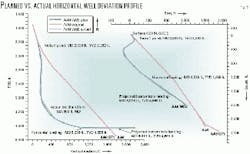
Fig. 5 shows the planned-vs.-actual well path, the actual taking a total of 4 days to "land" the horizontal and run the liner. The corresponding rate of penetration was 73 fph. After 51/2 in. casing was successfully set, crews successfully drilled 772 ft of 43/4 in. horizontal section, with minimal variance between the planned and actual well trajectory.
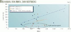
Figs. 6 and 7 illustrate the drilling efficiencies of the eight-well program. The plots of MRI and TD vs. drilling days show that most wells were in the best in class category.
Cost savings
Chevron calculated cost savings by comparing average drill and log costs for the eight-well program completed in 2000 with the costs for wells drilled in 1999.
Average drill and log costs per well in 1999 were $1.556 million and in 2000 were $0.642 million. Cost savings of $7.3 million are based on 2000 average costs subtracted from 1999 average costs, multiplied by 8.
The 1999 rig rates were adjusted upward to $29,000/day to ensure an objective head-to-head comparison.
Cost accumulation began when the wellbore was temporarily abandoned. This included removing all tubing and cementing a cast-iron bridge plug or retainer in place and finally pressure testing the casing.
Costs accumulation stopped when the last logging tool, either wireline or logging while drilling, was removed from the well.
The significant savings were made possible by team effort. The operator's sense of urgency to change from past, accepted drilling practices was the driver for reviewing the bit and mud selection, analyzing batch drilling practices, and modifying the geologic well path design.
References
The authors
Chad E. Williams is currently a production superintendent for Energy Partners Ltd., New Orleans. Previously, he worked as a drilling and workover superintendent and petroleum engineer for Chevron USA. Williams has a BS in petroleum engineering from Marietta College.
John S. Mason is an account manager for Baker Hughes in New Orleans, coordinating shelf and deepwater drilling systems operations in the Gulf of Mexico. Previously he held a variety of positions with Baker Hughes in the Middle East, Europe,and Houston. Mason joined Baker Hughes in 1974 and holds a BSc. (honors) degree in geology from London University.
John R. Spaar graduated with a BS (1976) in geology from the University of Miami. Employed by Hughes Christensen since 1988, Spaar has held several positions, including senior applications engineer, technical training coordinator, product engineer, and district engineer. He is currently working as area manager in Cabinda, Angola.
Based on a presentation to the SPE/IADC Drilling Conference, Feb. 27-Mar. 1, 2001, Amsterdam.

