Tests, field use support compression sleeve for seam-weld repair
First US use of a steel compression sleeve for pipeline repair confirmed nearly 7 years of Canadian and Mexican experience that the method can permanently repair longitudinal defects on an operating pipeline. The method is nonintrusive and requires no welding to the carrier pipe.
In comparison with a Type B sleeve, which relies on tapping through the pipe and the sleeve to reduce hoop stress, the steel sleeve applies compression to the carrier pipe to reduce the hoop stress and prevent crack growth.
Evaluation of the sleeve included measuring mechanical properties of the three different steels used in construction of AEC Pipelines Ltd.'s Platte pipeline, modeling of the stresses in the carrier pipe and in the sleeve, and full-scale testing.
The steel compression sleeve discussed in this article has been commercially available since 1994 and has been installed on 6-42 in. pipelines in Canada and Mexico, primarily to repair stress corrosion cracking, corrosion, and dents.
The US field program undertaken in 2000 and described here was the first use of this repair sleeve here.
Seam failures
The 932 mile, 20-in. Platte oil pipeline transports batches of crude oil from Casper, Wyo., to Wood River, Ill. It was constructed in 1951-1952 and hydrostatically tested before being commissioned.
Several seam-related failures occurred during early operations and resulted in hydrostatic testing of the entire line again in the 1970s. The hydrostatic test successfully removed other seam defects.
About 25% of the pipeline was hydrostatically tested again in the 1990s. Although a hydrostatic test at 125% of the maximum operating pressure (MOP) removes critical cracks, it does not remove all cracks, nor does it identify where remaining cracks are located.
These remaining cracks may extend in service because of fatigue and could eventually fail.
A 1997 seam-weld failure occurred in Nebraska and resulted in a US Office of Pipeline Safety (OPS) Corrective Action Order requiring inspection or hydrostatic testing of the A.O. Smith flash-welded pipe that makes up 60% of the line.
In early 1998, a transverse field inspection (TFI) tool was used to inspect the pipeline for long-seam weld anomalies. A subsequent field repair program in 1998 and 1999 focused on the A.O. Smith pipe and resulted in the removal of 469 cracks and some other defects by purging and cutting out (OGJ, Mar. 26, 2001, p. 54).
In 2000, an excavation program assessed other seam-weld anomalies identified by the TFI tool.
These locations were excavated and investigated with non-destructive examination. To maintain deliveries during the 2000 repair program, Platte wanted a permanent, non-intrusive repair method for seam-weld cracks.
The pipeline industry has traditionally used a pressurized, Type B sleeve to repair seam-weld cracks. This sleeve is welded to the carrier pipe and tapped through it and the sleeve to pressurize the annular space.
Platte had some reservations about welding repair sleeves to the carrier pipe and concerns over the possibility of internal corrosion between the sleeve and carrier pipe.
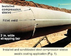
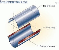
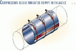
The company identified a steel compression sleeve as a possible repair system and evaluated it to determine if it could permanently repair seam-weld cracks. The steel sleeve, known as Petrosleeve, consists of two steel pipe halves with side bars (Fig. 1).1
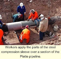
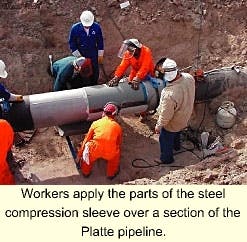
The two steel halves are installed over the defect, heated, and initially held in place with chain clamps or hydraulic jacks (Figs. 2 and 3).
The halves are then welded together with two longitudinal sidebars. No welds are made to the carrier pipe.
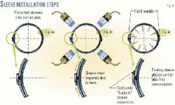
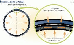
Fig. 4 shows a cross section of the mounted compression sleeve, along with the steps of the installation process. Fig. 5 shows how the internal pressure in the carrier pipe is balanced by the compression from the sleeve, to reduce the hoop stress in the carrier pipe.
Fig. 4, which illustrates the concept of this sleeve, shows how the thermal shrinkage of the sleeve induces a compressive stress component into the carrier pipe. The additional wall thickness also results in a lower stress level in the pipe.
The original circumference of the sleeve is reduced because the heated top half-sleeve slides farther underneath the sidebar than it would have done if it were cold. By being fixed in place with the field welds while it is still hot, the sleeve cannot return to its original diameter. Therefore, cooling will reduce the diameter.
During installation, an epoxy layer is applied between the sleeve and the carrier pipe. The epoxy acts as a lubricant when the halves are placed on the carrier pipe and later acts as a filler to transfer the load between the sleeve and the pipe evenly.
Several factors influence the degree of stress reduction in the carrier pipe. These include the pipe wall thickness and diameter, the sleeve wall thickness, the internal pressure during installation, and the installation temperature.
Pre-installation analyses that used proprietary software ensured adequate compression.2 Caliper measurements verify the compression after installation.
Testing program
For this program, Platte designed the installation temperature so that the carrier pipe would stay in compression from 0 to 100% MOP and prevent sleeved cracks from growing in service. This is safe and conservative because most small cracks would have a long remaining life under low cyclic tensile loads, even without a repair sleeve.
Before the sleeve purchase, the manufacturer works with the client to design the appropriate sleeve. This process considers the carrier pipe properties and operating characteristics. It determines sleeve wall thickness, grade, and detailed installation procedures that are then used in sleeve manufacture and installation.
During the manufacturing process, quality-control procedures include tracking the material certificates and serial number identification for each sleeve. The process employs certified welders and qualified welding procedures, uses pre-assembly validation of the sleeve, and uses non-destructive inspection of the carrier pipe. Custom manufacturing steps can be included to fit customer's requirements.
For Platte, a machined slot was provided on the inside of the sleeve to accommodate raised long-seam welds. Software is provided to the client to determine the target sleeve-installation temperature and to confirm that the desired amount of sleeve compression was achieved.
Requirements for installing the steel sleeve are as follows:
- Sandblasting the carrier pipe (the sleeve is already prepared).
- Trial fitting the sleeve around the pipe and marking the ends on the carrier pipe.
- Applying the epoxy around the pipe between the sleeve markings.
- Lifting the top of the sleeve onto the pipe.
- Lifting the bottom of the sleeve onto the pipe.
- Placing the three chains over the sleeve and tightening to the prescribed torque.
- Heating the sleeve to the predetermined temperature.
- Completing the field fillet welds.
- Allowing the sleeve to cool.
- Checking quality of installation with caliper measurements.
- Coating the sleeve.
- Backfilling.
A small field construction crew can install approximately one sleeve/hour. The installation crew typically consists of a grit-blasting crew, two welders, and two welders' helpers followed by a recoating crew.
Quality-control procedures require an inspector to monitor sleeve temperature during the heating process to ensure the required temperature. Verification of the achieved carrier pipe compression is by measurement of how far the two sleeve halves advance towards each other. This measurement is by calipers before the heating process and after the welding process.
Three sets of measurements on each side of the sleeve are recorded.
Technical approach
Installation of a compression sleeve effectively reduces the hoop stress on the sleeved cracks. It is well known that reducing the applied cyclic stress on a cracked component will in turn reduce the fatigue crack growth rate.
Fracture mechanics quantify the relation between the cyclic stress and crack growth rate. The fatigue crack growth rate (da/dN) in pipeline steels is described by the Paris Law, as follows:3
da over dN = C DK"where: a = Crack depthN = Number of cyclesC and n = Material constantsDK = Stress intensity factor range; this range is related to the cyclic change in internal pressure and hence hoop stress.Since DK is related to tensile stress in the carrier pipe and is effectively reduced to zero for compressive loading, the Paris Law predicts no crack growth for cracks under fully compressive loading.
A rigorous engineering analysis verified the ability of the sleeve to prevent cracks from failing on Platte's line pipe steels. The engineering analysis included:
- A review of previous installations and past test results.
- A review of ASME codes and US Department of Transportation regulations.
- Review of stresses in the installed sleeve and carrier pipe, using four separate stress-analysis models.
- Testing of mechanical properties of the steels (Charpy impact testing, tensile testing, fatigue testing, and chemical analysis) and of the epoxy grout (stress relaxation testing).
- Evaluation of sleeve installation parameters and quality control methods before, during, and after a full-scale installation.
- Full-scale cyclic fatigue testing.
The steel compression sleeve technology has been used since 1994 for repair of defects such as cracking, corrosion, and denting. More than 700 sleeves have been installed on pipeline systems in Canada and Mexico, on crude, LPG, and sweet and sour gas pipelines. The internal pipeline operating pressure during sleeve installation has varied from 0 to 1,600 psig.
Previous testing evaluated the compressive effect of the sleeve on the carrier pipe during installation and limited pressure cycling.4 In addition, testing was performed to determine crack progression (none), sleeve strength (burst testing), the strength of the side-bar welds, ability to repair dents, and pressure containment of through-wall defects.
Previous testing had not included full-scale, cyclic pressure testing.
Mechanical-property testing
The evaluation of the sleeve required testing and analysis of the three line-pipe steels used in Platte pipeline: A.O. Smith flash-welded (FW) pipe steel, Kaiser single submerged arc welded (SSAW) pipe steel, and Youngstown electric resistance welded (ERW) pipe steel.
The testing included Charpy V-notch impact testing, tensile testing, and fatigue testing. The chemical compositions of the steels were measured, and stress relaxation tests were performed on the epoxy grout. Individual tests were performed on specimens made from the seam-weld region, the heat affected zone (HAZ), and the base metals, so that the local mechanical properties could be measured.
Charpy V-Notch impact tests were performed to measure the transition temperature and impact energy as a function of temperature. Tensile tests and chemical analyses were performed to verify that the properties and compositions were within the specifications for each of the materials.
Fatigue testing was performed to determine the fatigue crack growth rates and the fatigue cracking threshold (DKthreshold) for the three steels and their seam-welds. Epoxy samples were subjected to compression testing under constant load to measure the strain as a function of time for different constant loading conditions at room temperature.
Full-scale testing
Two full-scale laboratory tests on pipe-sleeve assemblies investigated the behavior of the sleeve assembly under cyclic loading. The pipes tested were previously in-service linepipe and contained manufactured cracks.
The assembly was equipped with strain gauges and thermocouples that were spot welded to the carrier pipe and the sleeve and monitored digitally during the tests. In addition, temperature readings were taken during the installation, using temperature laser guns.
A sleeve was installed over the cracks in the shop, with the specified internal pressure and installation temperature for each test. Subsequently, the assemblies were tested with a 24-hr pressure hold at 1,168 psig (72% of SMYS), followed by a severe pressure cycling, consisting of 36,500 pressure cycles between 117 psig and 1,168 psig (7-72% of SMYS).
This corresponds to an R-ratio of 0.1. The number of cycles and the pressure range were selected to simulate one daily pressure cycle for 100 years of operation. Digital readings for the minimum and maximum pressures were verified with analog pressure gages.
Following the cyclic pressure tests, magnetic particle inspection verified that no cracks had formed in the sleeve sidebars, in the sidebar welds, or in the carrier pipe, close to the sleeve ends. Then, the sleeve was cut loose at 0 psig internal pressure, while the strains readings of all gauges were recorded.
From the strain values recorded during cyclic loading and the strain changes during sleeve removal, the stress conditions of the sleeve and pipe were determined for each test. After the sleeve was removed, a coupon was cut from the pipe around the defect.
Samples from the pipe underwent metallographic investigation to determine if the pre-existing defects showed crack growth during sleeve installation or during subsequent testing.
Test procedures
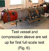
The first full-scale test was designed with a flaw that resembled the most severe flaw found during the 1998 TFI inspection.1 2 Fig. 6 shows the vessel, a 3-ft long sleeve around a 10-ft section of pipe with pipe extensions on both sides of the middle section and end caps.
The assembly contains an insert, which does not touch the wall of the carrier pipe, except for resting points near the end of the assembly. This insert reduced the volume needed to pressurize the assembly during the full-scale test, reducing the testing time.
The test was with a manufactured, longitudinal defect, along the center of the weld fusion line, in a 20-in. OD, 0.312-in. WT, X-52 Youngstown ERW pipe. A 12-in. long, 0.200-in. maximum depth (70% of pipe WT), through-wall, 0.030-in. wide flaw with a semi-elliptical depth profile was sleeved and tested.
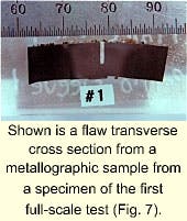
The flaw was calculated to be critical at a pressure of less than 50% of MOP, if no sleeve were present. This flaw was made with electric discharge machining and a root radius of approximately 0.5 mm (Fig. 7). The sleeve was 36-in. long with a 0.375-in. WT. The installation pressure was 100 psig and the specified installation temperature differential was 450° F.
During the cyclic portion of the test, digital data were recorded every 0.5 sec. After the test was completed, the sleeve was removed from the pipe, with all strain gauges active to record relaxation. The flaw area was then cut out for metallurgical and examination of scanning electron microscopy (SEM).
First a transverse cross-section was made for metallography. Then, the manufactured crack was broken open after immersion in liquid nitrogen to ensure a brittle fracture of the remaining ligament, and hence facilitate examination of the fracture surface with SEM.
The second full-scale test was performed with a manufactured, longitudinal defect, along the center of the weld fusion line, in a 20-in. OD, 0.312-in. WT, X-52 A.O. Smith FW pipe. A 4.0-in. long, 0.194-in. maximum depth (48% of 0.407-in. weld thickness), through-wall flaw was sleeved and tested.
This flaw was a manufactured fatigue flaw, with a sharp crack tip. The flaw was calculated to be subcritical at MOP, if no sleeve were present. The sleeve was 36-in. long with 0.375-in. WT. The installation pressure was 400 psig and the specified installation temperature differential was 370° F.
The pressurization occurred at 45 sec/cycle. Digital data were recorded every 0.5 sec. After the test was completed, the sleeve was removed from the pipe, with all strain gauges active to record relaxation. The flaw area was then cut from the pipe for metallurgical and SEM examination. The pipe sample was broken open with a similar procedure as used for the first full-scale test.
Mechanical properties
The chemical analyses and tensile tests performed on the three steels confirmed that the compositions and the strengths of the pipe samples were within their specifications. For all three steels, fracture occurred in the base metal and not in the welds, indicating higher tensile strength in the weld metal than in the base metal.
The Charpy V-notch impact test results showed that the three steels had variable toughness values that are generally low by comparison with present steel pipe. The weld fusion line had lower Charpy values than the heat-affected zone, and both had lower values than the base metal.
The fatigue crack growth test results showed that the fatigue behavior for the three steels was practically the same. The combined data indicated that for a given DK, da/dN was slightly larger for R-ratios of 0.5, than for R-ratios of 0.1. The results showed that DKthreshold is independent of R-ratio for the Youngstown steel, but that DKthreshold is influenced by changes in the R-ratio for the Kaiser and A.O. Smith steels.
The constant load compression tests on the epoxy showed that the epoxy exhibited creep at stress levels as low as 5% of its specified minimum compressive stress. From previous tests, it is known that the thickness of the cured epoxy between the carrier pipe and the sleeve is less than 1 mm and that there are many locations of metal-to-metal contact.
Therefore, the creep of epoxy layer is considered insignificant in comparison with the combined wall thickness of the sleeve and the pipe.
Testing results
The 24-hr pressure-hold period at the beginning of the cyclic test showed no changes (i.e., no drift) in the strain readings on the vessel. The pressurization initially occurred at 37 sec/cycle and later at 45 sec because of pump limitations.
A transverse cross section of the flaw revealed no fatigue crack growth. With SEM, no crack extension was found.
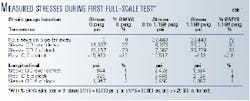
Table 1 shows the stress results from the first full-scale test. The strain gauges far from the sleeve indicated that the maximum hoop stress in the pipe was 72% of specified minimum yield strength (SMYS), as desired.
Transverse strain gauges on the exterior of the sleeve showed that the sleeve had taken over a portion of the tensile hoop stress that would ordinarily have occurred in the carrier pipe.
The hoop stress in the sleeve was about 35% of SMYS, while the measured hoop stress in the pipe under the sleeve was -0.8% of SMYS. A strain gauge on the inside of the carrier pipe, at the center of the sleeve at the 6 o'clock position away from the manufactured defect, showed that the carrier pipe was in full compression, even at MOP.
Strain gauges mounted in the longitudinal direction showed that the longitudinal stresses in the pipe-sleeve assembly were small. A comparison of these measured strains (stresses) with those of the linear elastic model and FEA model, showed that the calculated and actual stresses were essentially the same.
The 24-hr pressure-hold period at the beginning of the second full-scale cyclic test showed no changes (no drift) in the strain readings on the vessel. A transverse cross section of the flaw revealed no fatigue crack growth.
Before the defect was sleeved, this vessel had been stored outside, and therefore it was expected that the existing (manufactured) fatigue crack surface would be covered by corrosion.
Further, a liquid dye penetrant was applied on the crack to mark the existing crack depth. Light microscopy of the cross-section specimen showed that there was no evidence of continuation of the existing fatigue crack.
In the second full-scale test, five strain gauges were mounted at the center of the sleeve (18 in. from the ends) on different locations around circumference. The strain readings showed results that varied by a factor of two, which indicates a non-homogeneity in the stresses around the sleeve.
Even if well applied, strain gauges will have an uncertainty of up to 3%. This, however, would not explain the observed variation in the data.
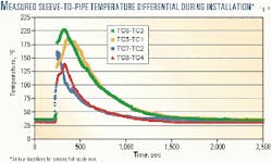
Fig. 8 shows the difference in temperature recorded during the second full-scale test, at locations on the sleeve exterior and the pipe interior. The figure shows that the temperature decreases rapidly after the burners are turned off and that the maximum achieved temperature difference was about 200° F.
Subsequent strain gauge and caliper readings showed that the achieved temperature differential was sufficient to bring the carrier pipe into full compression, as planned. This verified the manufacturer's installation software.
Therefore, if the same procedure were followed during a field application, the carrier pipe would be expected to be in full compression.
Field application
Between October 2000 and January 2001, 295 excavations were made on the Platte pipeline to investigate possible cracks, corrosion, and dents between Casper, Wyo., and Wood River, Ill.
Only 15 of the 295 excavations involved removing pipe as a repair method; the steel compression sleeve was the planned repair method for the remaining 280 excavations. A total of 209 steel compression sleeves was successfully installed on the pipeline while it delivered oil. These repair sleeves were installed over 209 seam-weld cracks, 22 dents, 9 gouges, 2 grinds, and 7 locations of corrosion.
Once the contractor, L. E. Bell Construction Co., Heflin, Ala., had mobilized to the site, a 1-day formal training course was presented to the contractor's sleeve installation employees, management, and Platte's inspectors, by the sleeve manufacturer.
The formal course consisted of one half day in a classroom followed by one half day of sleeve installation that used a pipe set up on skids at a nearby pump station. The sleeve manufacturer's trainers then spent the next few days shadowing the contractor's installation crew.
The contractor was required to use a written sleeve installation specification that included a welding procedure. The repair method was designed so that the carrier pipe would stay in compression at 0-72% of SMYS. In order to achieve this goal, the contractor had to meet a predetermined amount of sleeve compression.
Because the pipe wall thickness, sleeve wall thickness, and pipe temperature were essentially constant for the entire job, the amount of sleeve compression was a function of the internal carrier pipe pressure at the location of installation and the temperature to which the sleeve was heated.
Charts provided to the contractor and inspectors showed the required, or target, sleeve temperature as a function of internal pressure that would result in the carrier pipe under the sleeve being in compression up to 72% of SMYS.
Inspectors used calipers to verify that the required amount of sleeve compression was achieved by taking measurements before heating the sleeves and following welding.
Although the steel compression sleeve system had previously been installed on in-service pipelines up to 1,600 psig, Platte decided to limit installation pressures to less than 500 psig to ensure achievement of the designed sleeve compression and enhance worker safety.
One limitation of the steel compression sleeve arises from the fact that it fits over the carrier pipe so tightly as to make installations on bends unfeasible.
Two contingencies were to handle repairs on bends. First, some traditional Type B repair over-sleeves (with a standoff and resulting annular space) were ordered before the job started. Secondly, some half-length steel compression sleeves, 18-in. long, were ordered to accommodate gentle bends, which a 36-in. standard sleeve might not be able to accommodate.
By the end of the job, five short steel compression sleeves were installed, but no over-sleeves were required.
Because the A.O. Smith and Kaiser pipes had raised long-seam-welds and the Youngstown did not, 75% of the sleeves were ordered with a bull-nose slot ground in the top half of the sleeve. A sleeve with a slot could be installed on the Youngstown ERW pipe, but sleeves without slots could not be installed on the A.O. Smith FW and Kaiser SSAW pipe.
Finite-element analysis had shown residual stresses in the carrier pipe extending several inches past the end of the sleeve. While this analysis showed these residual stresses to be relatively small, Platte decided not to install a sleeve end within 6-in. of a girth weld.
For repairs required near a girth weld, the contractor ground a bull-nose slot circumferentially in the two sleeve halves prior to installation and straddled the girth weld with the sleeve. Nine such installations were performed in this repair program.
The contractor's crews were structured to maximize production. Front-end crews excavated the pipeline at the pre-staked locations.
Platte supported the front end with the addition of a survey crew who restaked sites where markers had been knocked down and were able to assist with any improperly staked sites. Following the NDE of the pipeline at the excavated site, the contractor's sleeving crews would install a repair sleeve if required. Finally, the back-end crews recoated the exposed pipe and backfilled the location.
Installation of a steel compression sleeve takes an experienced crew approximately 1 hr. Because of set up time and travel time between sites, three sleeves were installed per crew on a typical day. The maximum number of sleeves installed by one crew in a single day on this job was six.
The field installation program was successful. Platte saved significant dollars by avoiding the time and expenses associated with nitrogen purges and pipe cutouts. Additionally, Platte was able to maintain crude oil deliveries at near normal levels throughout the repair program.
More installation requirements
Although the focus of the repair method was concerned with repairing the pipe while product flowed, repair of the pipe while it was not flowing was overlooked.
Because the pipeline delivers crude oil batches at several locations, other locations downstream of the delivery points may have no flow for several hours at a time. While this condition was less common than the regular flow condition, it still resulted in standby costs being paid when sleeves could not be installed.
Although a temperature differential between the sleeve and carrier pipe is required to achieve the designed compression upon cooling, it seems intuitive that a 20-in. pipe full of oil behaves as a heat sink. It was hypothesized that the temperature difference between the sleeve and carrier pipe in the no flow situation would either:
- Be substantially the same as with flow and therefore permit sleeve installation with or without oil flow; or,
- Be somewhat less than in the case of oil flow but could be overcome by heating the sleeve to a somewhat higher temperature than for the oil flow installation case.
Shortly after completion of the field portion of the job, Platte and the sleeve manufacturer Petro-Line conducted a shop-based installation of a steel compression sleeve on Platte pipe filled with static oil.
Several temperature sensors at the 12:00 and 6:00 o'clock positions inside the carrier pipe were monitored throughout the installation process and compared with externally taken sleeve temperatures.
Analysis of data from this instrumented test revealed that it is possible to install a sleeve with no change to the present procedure (i.e., no additional heat required), although it is likely that there is a maximum internal pressure beyond which installation would be impossible because the carrier pipe starts to warm up after the heat is applied.
No interruptions
A subsequent field program using this sleeve was successfully completed with no interruptions to delivery.
For the current program, the sleeve installation was designed so that the carrier pipe would stay in compression from 0 to 100% MOP, in order to prevent sleeved cracks from growing. This is a safe and conservative approach because most small cracks would have a long remaining life under low cyclic (tensile) loads, even without a repair sleeve.
References
- Smyth, R.J., "Repairing Pipe Defects (Cracking, Arc Burns, Corrosion, Dents) Without Operational Outages Using the PETROSLEEVE Compression Sleeve Repair Technique," International Pipeline Conference, ASME, 1998.
- PETROSLEEVE Engineering Installation Parameters, V. 2.0, Petro-Line Construction Group, 2000.
- ASM Handbook: Fatigue and Fracture, Vol. 19, ASM International, Materials Park, Ohio, 1996.
- PETROSLEEVE Historical Test Results and Data, PETROSLEEVE Inc., Nisku, Alta., 2000.
- Vieth, P. H., Mesloh, R. E., Maxey, W. A., "Examination of Fracture Surfaces - Phase II Burst Tests," Kiefner & Associates Inc., December 1998.
The authors
Michiel P. Brongers is a project engineer with CC Technologies Inc., Dublin, Ohio. His work includes failure analyses, remaining life assessments, and fitness-for-service analyses. He received an MS in materials science and engineering from Delft University of Technology in The Netherlands and is a member of ASME and NACE.
Clifford J. Maier is a staff engineer with CC Technologies Inc., Dublin, Ohio. Before joining CC Technologies, he was an engineer for Salient Systems Inc. He received his bachelor in engineering technology in applied science from the University of Toledo and is a member of ASME and NACE.
Carl E. Jaske is a senior group leader with CC Technologies Inc., Dublin, Ohio. Before joining CC Technologies, he was a senior research scientist at Battelle, Columbus. He received a BS in general engineering, a BS in mathematics, and an MS in theoretical and applied mechanics from the University of Illinois and a PhD in metallurgical engineering from Ohio State University. Jaske is a professional engineer in Ohio and Alaska, an ASME Fellow, and a member of ASTM and NACE.
Patrick H. Vieth is a senior group leader with CC Technologies Inc. Dublin. Before joining CC Technologies, he held positions with Battelle and Kiefner & Associates Inc. Vieth holds a BS in mechanical engineering from Ohio State University and is a member of NACE and ASME.
Mark D. Wright is senior integrity engineer for AEC Pipelines Ltd., Calgary, owner of Platte pipeline. From 1997 to 2000, he was senior corrosion engineer for TransCanada PipeLines Ltd. and served as coating specialist in 1997 for Nova Gas International in Villahermosa, Tab., Mexico. From 1992-1997, he was a corrosion engineer for Nova Gas Transmission, Calgary. Wright holds a BASc (1992) in metals and materials engineering from the University of British Columbia, Vancouver, and is a registered professional engineer in Alberta and a member of NACE.
Robert Smyth is vice-president for engineering, Petroline Group, Nisku, Alta. For the past 10 years, he has been directly involved with the rehabilitation of oil and gas pipelines. Smyth received a BS (1965) in mechanical engineering from Queen's University, Kingston, Ont., Canada. He is a registered professional engineer in Alberta.
