Sulfur wash removes soot from Claus catalyst bed online
Saudi Aramco has successfully removed soot and restored normal pressure drop in a Claus catalyst bed with an online sulfur wash technique.
During the sulfur wash, the affected catalyst bed is operated at less than the sulfur dew point for a time and then regenerated to remove the accumulated sulfur.
This technique, which has been used repeatedly, does not permanently damage catalyst activity. This article presents the experience of Saudi Arabian Oil Co. (Saudi Aramco) with sulfur wash to remove soot from Claus converters in sulfur recover units (SRU).
Discussed are the causes of soot formation, methods to minimize it, the sulfur wash concept, sulfur wash procedure, and the results of a successful sulfur wash.
Problems
There are two types of Claus catalyst hydrocarbon fouling, one caused by heavy hydrocarbons and the other caused by light hydrocarbons.
A heavy hydrocarbon's breakthrough to a Claus converter results in formation of a very dark, glossy deposit which coats the outer surface of the catalyst sphere and blocks access to the catalyst active sites.
This type of contamination can only be removed by a "regenerative" burn off or by replacing the affected catalyst.
The other type of hydrocarbon contamination is a light, powdery carbon (soot). This type of contamination results from substoichiometric burning of light hydrocarbons in the reaction furnace or the fuel gas direct-fired reheater. It can also result from cracking of CS2.1
The acid-gas feed introduces light hydrocarbon components into the sulfur plants as impurities. Light hydrocarbons are also introduced during fuel-gas firing in the reaction furnace during the start-up of sulfur plants as an intermediate stage before introduction of the acid gas. Fuel-gas firing is also required during shut down of the unit just after the acid gas is cut.
Furthermore, continuous fuel-gas firing can also be encountered on the fuel gas direct-fired reheater upstream of the catalytic converters. Light hydrocarbon may also be injected in the reaction furnace continually in some plants to increase the furnace temperature to destroy acid-gas contaminants, mainly heavy hydrocarbon components (BTX).
Substoichiometric burning of light hydrocarbons causes production of powdery or sooty carbon, which accumulates in the downstream catalyst bed.
While this type of fouling does not normally hinder the activity of the catalyst bed because of its high surface area, it may result in excessive pressure drop. This high pressure drop will reduce plant throughput and may cause sulfur rundown-seal blowout, resulting in H2S exposure. Soot contamination may also result in the production of off-spec black sulfur.2
High pressure drop across any converter typically indicates the buildup of high quantity of soot on that catalyst bed. Carbon will also react with SO2, which is available in the process.
This reaction, however, is not quick enough to solve the problem before it propagates. To get a 10% reduction in the pressure drop across a converter can take weeks.1
The most common practice to remove this soot is by mechanical means after unit shutdown.1 2
Unscheduled shutdown of a sulfur plant can be costly in addition to the possible environmental impact due to acid-gas flaring. A typical Saudi Aramco sulfur plant takes 10-14 days for shutdown and start-up in addition to the time required to replace the catalyst.
With the sulfur-wash technique, Saudi Aramco has successfully removed soot and restored normal pressure drop across the catalytic converter without a shutdown.
Basic Claus process
A typical Claus unit consists of a thermal stage followed by two or, more commonly, three catalytic stages. Some type of reheat is provided before each catalytic stage. Fig. 1 shows a typical Claus unit.
The thermal stage consists of a reaction furnace (RF), waste heat boiler (WHB), and a condenser.
In this stage, one third of the feed H2S is burned to SO2. Sulfur is produced in the RF and then condensed by the first condenser. A large amount of heat is also generated in this thermal stage, most of which heat is recovered in the WHB.
The main chemical reactions are:
3H2S + 3/2 O2> SO2 + 2H2S + H2O
3H2S + 3/2 O2> 3/2 S2 + 3H2O
2H2S + SO2> 3/2 S2 + 2H2O
The generated SO2 in the reaction furnace then reacts over the catalyst with the remaining H2S to form elemental sulfur. Cooling and condensation remove this from the process gas in the condensers.
The catalytic reactors increase the sulfur conversion by reacting the generated SO2 with H2S over a catalyst bed according to the following chemical reaction:
2H2S + SO2> 3/x Sx + 2H2O
This catalytic stage, which consists of a reheater, catalytic reactor, and condenser, repeats two or three times to achieve the maximum sulfur recovery.
Depending on the acid-gas feed H2S percent and the reaction furnace configuration, the sulfur conversion in the RF can reach up to 75%.1 The rest is recovered in subsequent catalytic stages.
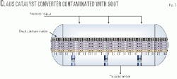
Fig. 2 shows a typical catalyst converter. It consists mainly of 3-4 ft of rectangular activated alumina catalyst bed. The catalyst bed is typically covered by 3-6 in. of bigger support alumina balls to hold the catalyst and distribute the gas.
Another support ball layer is used at the bottom of the catalyst bed to support the bed. This layer is on top of a wire mesh to prevent catalyst migration to condensers. The entire bed is supported by a support grating.
Contamination sources
Burning hydrocarbon with insufficient air results in sooty smoke. Substoichiometric firing in the sulfur plant will result in carbon fouling of the catalyst beds.
This carbon fouling is of a powdery or sooty type and normally accumulates on the top of the catalyst bed. Such fouling is typically limited to the top layer of the catalyst (Fig. 3); therefore, it results in little or no overall loss of catalyst efficiency.
In all the soot-formation cases encountered by Saudi Aramco, there was no obvious effect on catalyst activity by the accumulation. Overall plant performance will suffer if carbon deposits cause excessive pressure drop or sulfur contamination.
There are three potential sources of hydrocarbon/soot contamination in sulfur plants:
- Hydrocarbons carried over with acid gas from amine units to the reaction furnace.
- Carbon soot from the reaction furnace during fuel-gas firing.
- Carbon soot from fuel-gas direct-fired reheaters.
The latter two sources are the major sources of carbon deposits experienced by Saudi Aramco. These were caused by calibration problems with fuel and air meters.
Major upsets in the upstream sweetening units could contribute to this problem but this has not been experienced by any Saudi Aramco plants.
Hydrocarbon carryover
The hydrocarbon level in the acid gas from the gas treating can range from 0.07 to 3.5%.1 This amount can be handled by extra air in the reaction furnace through the combustion-air control logic.
During upsets in the upstream gas-treating units, however, high hydrocarbon levels can accidentally be carried over with the acid gas from the amine regenerator. Should this happen, the combustion air provided to the reaction furnace is not adequate to combust these hydrocarbons; therefore, soot may form and contaminate the first catalytic bed.
Depending on the amount of hydrocarbon breakthrough, the pressure drop across the first catalyst bed will start rising gradually until excessive pressure buildup is encountered.
The complete combustion of light hydrocarbons when they reach the sulfur plant with the acid gases (H2S and CO2) can be presented in these combustion reactions:
C3H8 + 5O2>3CO2 + 4H2O
C2H6 + 7/2 O2>2CO2 + 3H2O
CH4 + 2O2>CO2 + 2H2O
Similarly, the combustion of H2S in the reaction furnace can be represented in the equation:
H2S + 3/2 O2>SO2 + H2O
It is clear from these equations that much more air is needed in the reaction furnace completely to oxidize light hydrocarbons in addition to the H2S.
But air is not always available to oxidize these components when a high quantity of hydrocarbon vapors reach the reaction furnace, causing soot formation. The possible soot formation mechanism from the light hydrocarbons can be represented as follows:
CH4 + O2>C(s) + 2H2O
C2H6 + 3/2 O2>2C(s) + 3H2O
C3H8 + 2O2>3C(s) + 4H2O
The soot formation by this mechanism is uncommon because it results from an upset in the upstream gas-treating units for an extended time and it requires introducing large quantities of hydrocarbons with the acid.
Soot from reheaters
Fuel-gas direct-fired reheaters are used when steam is unavailable and the use of acid-gas direct-fired reheating is impractical. Fuel gas is typically fired in the reheater at about 95-97% of stoichiometric condition to avoid O2 breakthrough to the downstream catalyst beds.3 Steam is injected to suppress the soot formation in the effluent gas from the reheater.
Based on Saudi Aramco's experience, a steam-to-fuel-gas ratio of 0.2-1 lb/lb is effective in suppressing soot formation in the fuel gas direct-fired reheaters at the substoichiometric firing ratio of 90-95%.
Unlike other soot-formation mechanisms due to hydrocarbon carbon carryover from the amine plant, the soot formation from direct-fired reheaters can affect the second or third catalytic stage.
This type of soot contamination problem was encountered at one of the Saudi Aramco sulfur recovery units that uses fuel gas direct reheaters. Poor flow measurement of air or fuel gas resulted in soot formation from the reheater.
Improper sizing and installation of meters and control valves for fuel gas and combustion air could result in a ratio control problem.3
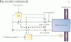
Fig. 4 shows a schematic for a fuel-gas direct-fired reheater with air/fuel control scheme and continous steam injection.
Soot from reaction furnace
Fuel-gas firing in the reaction furnace occurs during start-up and shutdown of sulfur plants.
This is an intermediate stage before introduction of the acid gas during start-up and after cutting the acid gas during the shutdown of the unit.
During this process, the fuel is typically fired at 95-97% of stoichiometric air ratio.2 The slight substoichiometric firing is to minimize oxygen breakthrough to the catalyst.
Severe soot formation could occur in the reaction furnace and would be carried over to the first catalyst bed during fuel-gas firing as result of firing with significant air deficiency.
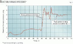
Fig. 5 shows a sharp increase in the reaction-furnace pressure in a sulfur plant during fuel-gas firing during start-up. The pressure increased rapidly from about 1 to 5 psig because of soot build up in the first converter. A pressure drop of about 4 psig occurred across the bed.
There are two possible reasons for this situation:
- Severe inaccuracy in the air or fuel gas streams measurement. This could result during use of over-sized or under-sized line to supply air or fuel during fuel-gas firing.
- Failure to adjust for the changes in the fuel-gas quality such as composition and pressure. In some plants, the quality of the used fuel gas can change dramatically. This could result in severe air/fuel gas ratio control if not accounted for in the flow controls.
Minimizing contamination
The best method to resolve the soot formation problem is to prevent the formation of soot. This can be done by:
- Minimizing hydrocarbons carryover with acid gas from gas-treating units. This problem may be encountered during the start-up or shutdown of the gas treating units.
During these stages a careful monitoring of the acid-gas hydrocarbon level should be conducted.
- Ensuring reasonably accurate metering of the air and fuel gas streams. It is also recommended to control both streams with good quality control valves.3
- Routine monitoring of flame through the peep sight in the reaction furnace and direct-fired reheaters to ensure adequate combustion and no soot formation.
It is possible to detect air-deficiency combustion by the color and shape of the flame.
- Steam injection during substoichiometric fuel-gas firing to prevent soot formation.
Saudi Aramco injects steam during fuel-gas firing to the reaction furnace and also continuously in the fuel-gas direct-fired reheaters.
- Installing a hydrocarbon analyzer on the feed acid-gas stream to detect high hydrocarbon levels in the acid gas.
- If the fuel-gas quality changes frequently, then it is essential to adjust for these changes in the air-fuel gas ratio control.
- Using indirect steam reheaters or acid-gas fired reheaters as an alternative for direct fuel gas-fired reheater for new design.
Detecting contamination
A pressure-drop survey detects catalyst soot contamination. Typically excessive pressure drop across converters indicates soot buildup on the top of the catalyst bed.
The reaction-furnace pressure, which is closely monitored, gives the first indication of a problem. The rapid increase in the reaction furnace pressure during normal operation or during fuel-gas firing indicates a high pressure drop across one or more catalyst beds.
A pressure-drop survey would help identify the affected catalyst bed. Once the affected bed is identified and the cause of soot formation is corrected, a sulfur wash can resolve the high pressure problem.
Principle of sulfur wash
The sulfur wash is based on the commercial sub-dewpoint process used to extend the Claus process to achieve higher sulfur recovery. Operating the catalytic reactor below the sulfur's dewpoint achieves this.
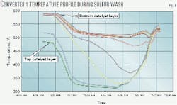
Examples of this technology include the CBA (Amoco Cold Bed Adsorption), the MCRC (Delta Hudson), and the Sulfreen (Elf Aquitaine) process.4 Fig. 6 shows the temperature profile for a catalyst converter while operating below the sulfur dewpoint during a sulfur-wash operation.
This figure shows the temperature-drop propagation through the catalyst bed with time after start of the sulfur wash.
During the sulfur-wash process, the converter operates below the sulfur dewpoint.
This means that the produced sulfur, which is in vapor phase, will condense and remain in the catalyst bed as liquid. As more sulfur is produced, it will flow by gravity through the bed, flushing the soot from the bed to restore the normal pressure drop.
This processes takes 7-20 hr, depending on the amount of soot buildup, the size of the catalyst bed, and the amount of sulfur produced in the converter. Fig. 7 shows the pressure drop across Converter 2 and the time needed to restore the normal operating pressure drop through this converter. This case required about 20 hr to restore the normal pressure drop.
The more sulfur being produced in the contaminated converter with respect to the catalyst quantity, the faster the sulfur wash process will be.
Theoretically, it is possible to fill all the pores in the alumina catalyst with sulfur. At this point, however, the H2S/SO2 conversion across the catalyst is minimal, which means that continuing the sulfur wash after this point is of minimum value.
An operator should restart the reheater and repeat the sulfur wash if this point is reached without the high pressure drop being completely eliminated.
Commercial sub-dewpoint beds typically run to about 35 wt % sulfur loading with good H2S/SO2 conversion up to this loading. Loading the catalyst to 35 wt % can be used to calculate the maximum expected duration of the sulfur wash.5
The amount of sulfur produced from a particular converter can be estimated with a sulfur simulation package or by a direct measurement based on the rundown flow of the condenser associated with that converter.
The catalyst weight is estimated based on the bed volume and the bulk density supplied by the catalyst manufacturer. It is important that the catalyst bed supports are capable of handling the extra weight of the sulfur, which will condense during the sulfur wash.
Sulfur-wash procedure
Following are the major steps to conduct sulfur wash:
- Before starting the sulfur wash, reduce the liquid sulfur level to a minimum in the receiving pit. This is to minimize the amount of liquid sulfur, which will be contaminated with the flushed carbon. Saudi Aramco has experienced no major sulfur contamination problem when conducting the sulfur washes.
- The sulfur-wash is started by the catalyst bed inlet temperature gradually being reduced by 50° F./hr until the minimum operating conditions for the reheater are reached. At this stage, the reheater can be completely isolated.
- During the sulfur wash process, the pressure drop across the converter should be monitored and recorded. The reheater burner is likely to be offline for 7-20 hr, depending on the converter being sulfur washed. Converter 1 usually takes the shortest time, and Converter 3 takes the longest.
- The reheater should be restarted when the normal pressure drop is restored or the maximum sulfur loading is reached. The converter inlet temperature should be increase gradually (50° F./hr) until reaching the normal operating temperature. It is at this point that we expect to see black sulfur.
This controlled increase of temperature will prevent a sudden increase in liquid sulfur flow. - A heat soak of the catalyst should follow the sulfur wash.
Condensed sulfur in the catalyst pores can cause a severe catalyst deactivation. The condensed sulfur during the sulfur wash can be easily removed to restore the catalyst activity by the converter being raised to greater than the normal operating temperature.
The converter temperature should be increased by 25-50° F. above the normal operating temperature. Other procedures call for achieving an outlet temperature of 650-750° F. in the first converter.
The second and third converters should reach 100-120° F. above their normal operating temperatures. The heat soak should be maintained for 24-36 hr.5 Based on our experience, this should be adequate to restore the same catalyst activity as before the sulfur wash.
This procedure may be repeated if the catalyst activity was not fully restored.
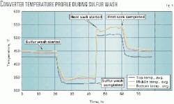
Fig. 8 shows the major steps of the sulfur wash. The data in this figure are from a sulfur wash that was conducted to remove soot buildup from Converter 1. This converter was operating at an inlet temperature of 450° F.
The reheater was shut down for about 24 hr to perform a sulfur wash to resolve excessive pressure drop across the converter. The catalyst then underwent heat soak to remove the accumulated sulfur.
The converter was returned to normal operation following the heat soak.
Fig. 9 shows the reaction furnace pressure and converter temperature as a function of time for a successful sulfur wash conducted by Saudi Aramco.
In this particular case, the reaction furnace pressure was high due to excessive pressure drop across the first converter as a result of soot buildup. The normal reaction furnace pressure for this plant is about 1.5 psig.
The sulfur wash started when the reaction furnace pressure was about 5 psig. The pressure started dropping as the converter temperature reduced. The normal pressure drop across the converter was fully restored in about 13 hr.
Results
Claus catalyst soot contamination is a potential problem that could lead to unscheduled unit shutdown and subsequent business interruption and revenue losses.
This can be avoided by using sulfur-wash procedure techniques to remove soot contamination online.
Saudi Aramco used this technique successfully several times to remove soot from catalyst beds online and to restore the normal pressure drop.
This technique is simple and has no major impact on the catalyst performance.
The best way to solve this problem, however, is by preventing soot formation in the first place.
Saudi Aramco's experience indicates this problem can be prevented in most cases by taking certain basic steps during fuel-gas firing in the reaction furnace or when using a direct-fired reheater.
The key factor in preventing soot formation is ensuring the correct fuel-to-air ratio. This can be done by ensuring accurate measuring of air and fuel gas flows, minimizing carryover of high hydrocarbon with acid gas, and accounting for any changes in the fuel-gas conditions.
References
1. Paskall, H.G., "Capability of the Modified Claus Process," Final Report to the Department of Energy and Natural Resources of the Province of Alberta, Western Research, 1979, pp. 47-67.
2. Norman, S. William, "Claus Sulfur Plant Operation For The Maintenance of Catalyst Activity," Kaiser Aluminum & Chemical Corp., Baton Rouge, La., pp. 5-6.
3. Goar Gene, "Haunting Problems in SRU's with Handy Solutions for What to Do," reprint of a paper given at The International Sulphur '96 Conference, Vancouver, BC, October 1996, pp. 12-16.
4. Lieberman, Norman P., Troubleshooting Natural Gas Processing, 3rd edition, pp. 154-57.
5. Pearson Mike, "Claus Catalyst Management," presented at Sulfur Recovery Symposium, Brimstone Engineering Services Inc., Sept. 20, 1995, Vail, Colo., p. 7, and various email correspondence with the author.
The authors
Mohammad N. Al-Haji is a process engineer with the Saudi Arabian Oil Co. (Saudi Aramco) process engineering division. He has worked in gas processing for about 10 years. His main area of expertise is gas sweetening and sulfur recovery. Al-Haji is involved with troubleshooting of existing plants and design of several new sulfur-recovery plants for Saudi Aramco. He graduated from King Fahd University of Petroleum & Minerals with a degree in chemical engineering in 1992.
Abdulhadi M Al-Adab is a process engineer at Saudi Aramco's Shedgum gas plant. He began working for Saudi Aramco in 1991, and most of his experience is in sulfur recovery. He graduated from King Fahd University of Petroleum & Minerals in 1991 with BS in chemical engineering
Based on a presentation to the 51st Annual Laurance Reid Gas Conditioning Conference, Norman, Okla., Feb. 25-28, 2001.


