PERMAFROST PIPELINING - 1: Northern Canadian pipeline deals with effects of soil movement
The entry of hypermarts into the US gasoline retail business shifted into high gear in 2000 and will continue its pace in the next decade.
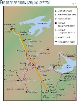
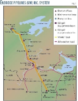
The line moves crude oil from Norman Wells, NWT, to Zama, Alta., and its route follows a portion of the Mackenzie River Valley in the Northwest Territories.
This route runs through discontinuous permafrost that can interact with the pipeline through frost heave, slope movement, and thaw settlement that can produce extreme structural stresses in the pipe wall.
Given the proper conditions, these stresses may localize and the pipeline will deform plastically, causing pipe wall wrinkling.
This first article in a series of two on the effects of permafrost reviews the general structural design of the pipeline and discusses the inspection and monitoring of its structural integrity, as well as the intervention criteria used to determine when structural mitigation is required.
The discovery of a wrinkle from internal inspection pig data will be discussed along with field dig verification, installation and monitoring of field instrumentation, and the resulting pipeline repair technique.
The concluding article next week will discuss instrumentation installed before and after the affected line pipe was replaced.
Fig. 1 shows the route of the Norman Wells-Zama pipeline. Enbridge owns and operates the pipeline that has a design capacity of about 5,000 cu m/day and a maximum operating pressure of 9,930 kPa.
The pipeline was primarily built during the winters of 1983-1984 and 1984-1985, with the pipeline put into operation in April 1985. It was the first fully buried pipeline through discontinuous permafrost in North America.
The mechanical and structural analysis of this pipeline posed unique challenges to designers. Its route crossed a variety of terrains that could impart extreme stresses to the pipeline.
The discontinuous permafrost subjects the pipeline to frozen and unfrozen interfaces that cause strains and curvatures to develop due to differential settlement. Additionally, the pipeline route traverses many slopes, the effect of whose movement on the structural response of the pipeline had to be addressed.
Design criteria
The concept of the Norman Wells-Zama pipeline was to design and operate an arctic pipeline that disturbs the environment as little as possible. The pipeline was to be operated at ambient ground conditions, with the exception of the segment near Norman Wells.
The oil is chilled at Norman Wells to reduce the effect on the permafrost for the most northern section of the pipeline. The Norman Wells crude, with a pour point of -30° C., can be pumped even in the coldest predicted surrounding ground temperatures of about -8° C.
Designing and operating an "ambient" pipeline system allows for limited degradation of the permafrost. Controlling the rate of permafrost degradation also allows control of the resulting differential settlement.
Further to reduce the effect of the pipeline on the environment, existing cut lines were used as much as possible. By use of existing cut lines, it was thought that the possibility of encountering permafrost in the first few meters of soil cover would be reduced, since the previous clearing activities had changed the surface thermal conditions causing the permafrost to thaw.
Additionally, slope stability was a concern, and an insulating layer of woodchips was utilized on the steeper ice-rich slopes to reduce the thaw rate.
Another unique design concept was to ensure the pipe could withstand plastic deformations.
The loadings on the pipeline were categorized as primary and secondary.
Primary loads are those independent of displacement and that do not diminish when yielding occurs. Secondary loads depend on displacement and tend to be self-limiting when yielding occurs.
Primary loads are similar in pipelines installed in both stable and unstable ground conditions. Secondary loads, however, can be different for a pipeline that is installed in stable ground compared to one that is installed in unstable degrading permafrost. A buried pipeline installed in degrading permafrost and subjected to differential settlement will experience secondary loading.
A variety of methods identified the loadings acting on the pipeline.
Field observations, borehole analysis, laboratory experiments, and computer modeling quantitatively defined the loadings. Elastic-analysis techniques were used in the analysis of the primary loadings (load-controlled), with the structural response governed by a stress criterion.
The elastic analysis utilized the maximum shear (Tresca) yield criterion. Inelastic analysis techniques were used in the analysis of the secondary loadings (displacement-controlled), with the structural response being governed by a strain criterion. The inelastic analysis utilized the distortional energy (von Mises) yield criterion.
Therefore, the design criteria considered both stress and strain limits to ensure the integrity of the pipeline. The combined circumferential and longitudinal stresses were limited on an elastic basis by the existing regulations of the time. The strains were limited on an inelastic basis by analytical methods and laboratory experiments.
The maximum longitudinal compressive strains were limited to prevent local wrinkling of the pipe wall. The maximum longitudinal tensile strains were limited to prevent excessive tensile yielding in the pipe wall.
The maximum longitudinal tensile strain was limited to 0.5%, and the maximum longitudinal compressive strain for a pressurized pipe to 0.75%. Design reduction factors of 0.667-0.889 of the design maximum were applied, depending on the loading conditions.
A finite-element interactive inelastic pipe-soil beam model verified the calculations of the pipe wall thickness for the most critical loading combinations.
Pipeline monitoring
A regular pipeline-monitoring program was part of the regulatory approval for this project. A weekly aerial line patrol visually inspected the pipeline right-of-way. Various instruments monitor the conditions of the pipe and right-of-way.
Typically during September, a reconnaissance trip along the right-of-way completes site investigations, instrumentation readings, and slope assessments.
Since 1989, the pipeline has been monitored annually by use of an internal inertial geometry tool (Geopig, currently owned and operated by BJ Pipeline Inspection Services). This tool is to detect pipe movement associated with slope instability and differential thaw settlement.
Enbridge compares the most recent Geopig results to previous Geopig runs. The 1992 Geopig data are being used as the data reference year because all subsequent runs since 1992 have been completed in September, the month of greatest thaw. The Geopig curvature data are used to calculate a horizontal and vertical bending strain as described by Czyz.1
Fig. 2 shows the Geopig data for the 1997 pipe profile at Slope 92 (KP 318). Fig. 2 also shows the bending strains (arising from curvatures in the horizontal and vertical planes), radius of curvature, and measured internal diameter.
Slope 92 performance
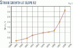
The geometry tool data that have been collected annually for the pipeline make it possible to examine strain growth. In 1989, the strain associated with Slope 92 was 0.2% and eventually grew to 3.16% before remediation (Fig. 3). In 1991, this slope was put on the "watch list" because of increasing strain and was scheduled to be visually inspected during the 1992 fall reconnaissance trip.
Slope 92 is a north-facing slope of approximately 16°, with the toe of the slope terminating at a creek. The slope is covered with an insulating layer of wood chips and has a wooden crib structure at its toe to keep the woodchips from entering the creek.
The reconnaissance trip in 1992 discovered tension cracks in the soil across the lower part of the slope. This led to further investigation including analysis of the Geopig data and an exploratory dig in March 1993.
The investigators determined "there was no apparent relationship between the tension cracks and the pipe," in findings from the investigative dig reported by Savigny.2
As part of the investigation, the pipeline profile was surveyed to determine the current strain values. It was determined that the strain values calculated from the pipe profile, at the time of excavation, correlated well with the 1992 Geopig data.
It was postulated that compressive stresses present in the pipe were relieved during the 1993 investigative dig. In 1997, however, the differential strain levels had increased and the annual Geopig run detected an ID change.
Review of the annual Geopig data depicted the evolution of a wrinkle. Several wrinkles as a result of similar combined internal pressure, axial load, and bending have been produced by testing the Norman Wells pipe in the University of Alberta Structural Engineering Laboratory.3 4
The characteristics that indicate a wrinkle has formed are (Fig. 2):
- A high value of the compressive bending strain.
- An increase in the ID at the same location.
Consequently, it appeared that a wrinkle existed at KP 318. A team was therefore assembled to investigate this pipeline anomaly.
Investigative dig
Enbridge, with AGRA Earth & Environmental Ltd. and the University of Alberta, scheduled an investigative dig for Slope 92 in February 1998. The purpose was to verify the existence of the wrinkle, complete nondestructive examination (NDE) near the wrinkle, and install monitoring instrumentation on the slope and pipe.
Slope-monitoring instrumentation would be installed to produce data over the next 12 months, with the pipe section being scheduled for replacement in February 1999.
Had the wrinkle not passed the NDE, a sleeve would have been installed over it as a temporary repair until the pipe section was replaced.
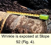
To determine the response of the pipe to overburden unloading, elevation surveys of the top of the pipe were completed as the pipe was being exposed. When the wrinkle was exposed (Fig. 4), the excavation was stopped, and elevation measurements were completed.
The geometry of the wrinkle is consistent with the characteristics of wrinkling displayed by the Geopig data described previously. A detailed comparison of this geometry with analytical predictions is presented in Yoosef-Ghodsi.5
The girth weld seen immediately down slope from the wrinkle and the wrinkle area were inspected with magnetic particle inspection and ultrasonic testing methods. The nondestructive examination revealed no cracking or laminations in the weld, wrinkle, and adjacent pipe. Therefore, the instrumentation was installed.
Instrumentation
Six types of instrumentation were installed to monitor movements of the pipeline and slope: pipe deflection indicators, slope movement indicators, soil settlement plates, deep well thermistor strings, strain gauges, and extensometers. Fig. 5 shows the instrumentation before backfilling.
The instruments were read monthly until February 1999, when the pipe section was replaced. The data showed further movement of the slope and pipe. Some of this movement, however, was associated with backfill consolidation.
A detailed account of the geotechnical analysis, instrumentation, and measurements of Slope 92 can be found in the conclusion to this series.
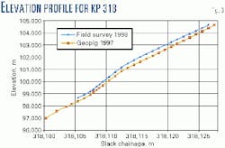
The investigative dig surveyed the pipe elevation profile and compared it with the Geopig profile. As Fig. 6 shows, the two profiles correlated very well.
The geometry of the local wrinkle was also measured in the field and again the comparison with the Geopig data correlated well.5
The field comparison with the Geopig data has strengthened the confidence in this technology. The ability to monitor and compare pipe curvature and strains as a result of differential soil movements is proving to be a powerful tool in assessing the performance of this pipeline.
Pipe replacement
The analysis and prediction of the structural behavior associated with the conditions of limiting compressive strains and localized wrinkling in pipelines due to slope stability and thaw settlement have been and continue to be studied extensively.
As part of the original design, research established the strain-based criterion wherein the pipeline may operate beyond the elastic limits of the material.6
More recently, the previously cited University of Alberta research used in conjunction with the Geopig data has proven valuable in predicting the probable pipe behavior associated with local wrinkling.5
Laboratory testing of the Norman Wells pipe went beyond the conditions at Slope 92, without the loss of containment.3 7
The geotechnical mechanisms that are acting on Slope 92, however, have yet to be fully analyzed and understood.
Although research is at present under way to determine failure conditions within wrinkles,8 the level of knowledge with regards to the limiting strains in local wrinkles is limited, and a proven method to determine the conditions of material failure has yet to be developed.
Therefore, the pipe joints upstream and downstream of the wrinkle at Slope 92 were replaced.
February 1999 was determined to be the best time of year to complete the replacement because:
- The site would not be accessible to heavy equipment in the summer months without severe damage to the right of way.
- There would be an increasing number of hours of daylight at that time of year.
- Reasonable temperatures would be expected.
- The allowable weights on the ice bridges would allow the mobilization of heavy equipment.
- The winter road to Norman Wells would be open, allowing Enbridge personnel stationed in Norman Wells to mobilize company equipment to the work site.
The remote and isolated construction site made it necessary to mobilize a temporary camp to the area to provide accommodations for the replacement crew.
Safety and environmental concerns also posed a challenge because of the remote location.
The location of the pipe replacement to a flowing creek required special attention be paid to environmental issues. Several regulatory agencies were contacted to ensure the project obtained all the necessary permits and approvals. Pre and post-construction environmental assessments were completed to ensure the project had a minimum impact on the environment.
Maintenance of service
Enbridge worked closely with Imperial Oil Ltd. in Norman Wells to schedule the pipeline shut down and determine the maximum length of time the pipeline could be out of service.
A 72-hr pipeline shutdown limit was set by Enbridge and Imperial Oil.
The Geopig pipe profile data (Fig. 2) were used to calculate the sag bend and overbend angles for the replacement pipe. The pipe was prebent and prehydro tested before being shipped to the construction site, where it was test-fitted adjacent to the excavated pipe (Fig. 7).
To complete the pipe replacement at Slope 92, the oil in the pipeline between mainline block valves at KP 291 and KP 328 was displaced by injection of nitrogen into the pipeline.
- Purging. Three solid case polyurethane purging pigs were launched from Norman Wells to facilitate the purge and line fill of the pipeline.
Pig No. 1 was used in the nitrogen purge, Pig No. 2 in the line fill, and Pig No. 3 as a backup. The pigs were fitted with rattling devices and radio transmitters to allow tracking.
The arrival of Pig No. 1 at KP 291 was critical to the construction schedule because the pipe replacement was to commence at first light. The nitrogen injection and blowdown were estimated to take 24 hr to complete.
Pig No. 1 was tracked into the mainline block valve at KP 291. Once the pig had passed the valve, the pumps at Norman Wells were shut off, the block valve at KP 291 was closed, and injection of nitrogen begun.
The scope of work for the nitrogen-injection contractor was to inject sufficient N2 to maintain a minimum suction pressure of 340 kPa at the Wrigley pump station (KP 336), while minimizing the final N2 pipeline pressure between KP 291 and KP 328.
Minimizing the final N2 pipeline pressure would in turn minimize the time required to blowdown the N2 in the isolated pipeline section to atmospheric pressure.
Once Pig No. 1 passed the mainline block valve at KP 328, the valve was closed and the pipeline was completely shut in.
The nitrogen pressure was blown down to atmospheric pressure through two vacuum trucks. The blowdown sites were at KP 291 and KP 328. The nitrogen blowdown took 6 hr.
- Excavation. The woodchips on Slope 92 were stripped from the slope and stockpiled. The creek at the toe of the slope was unfrozen and flowing. A 323-mm OD flume pipe was installed to maintain creek flow during the replacement.
Because the pipeline at the creek crossing was found to be about 4 m deep, special attention was paid to ensure the excavation was safe. Trench wall back sloping and spoil removal were required to maintain a safe trench.
- Replacement. The wrinkled pipe had a 6.91-mm WT, with the WT transitioning to 9.53 mm at the creek crossing. The replacement pipe was 323.9-mm OD, 9.53 mm WT, Grade 359, CSA Z245. 1-M95, Category II with a minimum absorbed energy of 27 Joules at -15° C.
Thus, the wall thickness was increased by 37% to increase the resistance to future wrinkling at this location. The pipe was coated with two layers of yellow jacket.
The replacement pipe, with the Geopig-calculated sag bend and over bend fit well.
Once the tie-in welds were completed, they were X-rayed and coated with a corrosion protection material.
The pipeline was bedded and padded with imported sand. The sand was compacted around the pipeline with a vibratory compaction attachment on the excavator. Once the sand was compacted, the native spoil material was used to backfill and the wood chips were replaced on the slope.
The pipeline was shutdown for 48 hr during the replacement project.
Post-construction instrumentation
As part of the ongoing analysis of the geotechnical mechanisms present at this slope, slope-monitoring instrumentation was installed in March 1999.
Two slope indicator casings and two corresponding thermistor strings were installed.
Each slope indicator casing and thermistor string was installed down to about 15 m below the top of the woodchips. The slope indicators monitor the slope movement at various planes down to 15 m below the woodchips.
The thermistor strings measure the ground temperatures at the various planes. A detailed summary of this instrumentation is presented in the conclusion to this series.
Confirmation of the Geopig data with field measurements, in terms of pipe profile and bending strains, is very significant.
It confirms that the technology exists successfully to monitor and track the progress of pipe curvatures in permafrost terrain conditions.
This "monitoring approach" to such design issues as thaw settlement, frost heave, and slope movement has been proven to be technically reliable.
Moreover, the recent research concerning the deformational behavior of girth-welded and line pipe has proven valuable in the prediction of pipe wrinkling in the Norman Wells pipeline.
With the further laboratory experiments and analytical research currently being carried out at the University of Alberta on pipeline strain limits, development of reliable techniques for assessing the risks associated with localized wrinkling is close.
Acknowledgments
The authors wish to thank Enbridge Pipelines (NW) Inc. for permission to publish this article and for its assistance in preparing for and replacing the wrinkled section of pipe. The authors also wish to thank Alan Hanna, Jim Oswell, and Alex Costin from AGRA Earth & Environmental Ltd., J.J.R. Cheng, D.W. Murray, Nader Yoo sef, and Shahab Afhami from the Univer sity of Alberta, and BJ Pipeline Inspec tion Services for their assistance in the study of the phenomenon at Slope 92.
References
- Czyz, J.A., Fraccaroli, C., and Sergeant, A.P., "Measuring Pipeline Movement in Geotechnically Unstable Areas Using An Inertial Geometry Pipeline Inspection Pig," ASME International Pipeline Conference, Calgary, 1996.
- Savigny, K. Wayne, Burgess, M.M., MacInnes, K.L., "Geothermal and Geotechnical Performance Slope and Wood Chip Insulation," Project Report 3, 1993.
- Yoosef-Ghodsi, N., Kulak, G.L., and Murray, D.W., "Some Test Results for Wrinkling of Girth-Welded Line Pipe," 14th International Conference on OMAE, Copenhagen, 1995.
- Murray, D.W., "Local Buckling, Strain Localization, Wrinkling, and Post-Buckling Response of Line Pipe," Engineering Structures, Vol. 19 (1997), No. 5, pp. 360-71.
- Yoosef-Ghodsi, N., Murray, D.W., Cheng, J.J.R., Doblanko, R.M., and Wilkie, S.A., "Analytical Simulation of Field Measurements of a Wrinkle on the Norman Wells Pipeline," International Pipeline Conference, ASME (OMAE Division), Calgary, Oct. 1-5, 2000.
- Workman, George H., "Summary Report: Pipe Wall Stability Analysis of 12. 75 inch OD X 0. 25 inch W. T. Grade 52 Pipe." Prepared for Canuck Engineering Ltd. (prepared by: Applied Mechanics Inc., Columbus, Ohio), 1981.
- C-FER. Compressive Strain Limits for Buried Pipelines, Confidential to Interprovincial Pipe Line Inc. Project 91-24, 1994.
- Das, S., Cheng, J.J.R., Murray, D.W., Wilkie, S.A., and Zhou, Z.J., "Laboratory Study of Wrinkle Development and Strains in Pipe from the Norman Wells Pipeline," International Pipeline Conference, ASME (OMAE Division), Calgary, Oct. 1-5, 2000.
The authors
Scott A. Wilkie is a project engineer with Enbridge Pipelines Inc. in Edmonton. He maintains and manages the monitoring and surveillance program related to the Norman Wells pipeline. Wilkie holds a BSc (1996) in civil engineering from the University of Alberta, and is a ® professional engineer in Alberta.
Richard M. Doblanko is an engineering specialist at Enbridge Pipelines Inc. with more than 12 years' experience in pipeline engineering, construction, and operations. He holds a BSc (1989) in mechanical engineering from the University of Alberta and an engineering design and drafting diploma from the Northern Alberta Institute of Technology (1980). Doblanko is a registered professional engineer and certified engineering technologist in Alberta.
Steven J. Fladager is an engineering specialist at Enbridge Pipelines Inc. with 14 years in pipeline project engineering and project management. He holds a BSc from the University of Alberta and is a registered professional engineer in Alberta.
Based on a presentation to IPC 2000, the International Pipeline Conference, Oct. 1-5, Calgary.
