Batch-inhibitor treatment size, shut-in time determined
Equations and graphs have been developed for determining how long wells should be shut in after a batch inhibitor treatment and how much inhibitor is required to coat the tubing in a well.
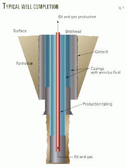
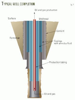
Fig. 1 illustrates a typical well completion.
To protect the tubing from damage caused by corrosion, operators periodically shut in wells and inject corrosion inhibitor solution down the production tubing. The objective is to coat the tubing surface with a corrosion inhibitor film.
One must know the falling film velocity to determine how long to shut in the well and the film thickness to determine the amount of inhibitor needed.
Falling film studies
References on falling film on the inner wall of a circular tube can be traced back to the 1930s. The studies were developed for heat and mass transfer analysis in the chemical processing industry, and the results are contained in many journals and engineering textbooks.1-7 These studies focused on the relationship between falling film velocity and film thickness.
In aboveground analysis, velocity can be directly measured by collecting the solution at the end of the tubing. This, however, is not the case for oil and gas wells because it is impossible to collect the film at the bottom of the well.
Another method, therefore, is required.
Liquid column
Falling film is a solution of corrosion inhibitor and its carrier that can be water, diesel oil, or hydrocarbon condensate. In some cases, a chemical is added to increase the solution density.
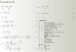
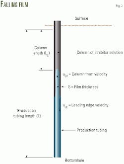
When the injection pump delivers the solution to the tubing string, a liquid column is built up at the top of the string (Fig. 2). Equation 1 (see equation box) is derived by applying a material balance to the solution.
In Equation 1, Lc is the length of a liquid column, Qpump is the volumetric flow rate of the solution pumped in to the tubing, and Qdrain is the volumetric flow rate of the solution drain-off.
In most cases, Qdrain is much less than Qpump. Equation 1, therefore, can be simplified by neglecting Qdrain. By integrating the simplified equation from t = 0 to tpump, one obtains Lc, the liquid column length. The tpump is the pumping time.
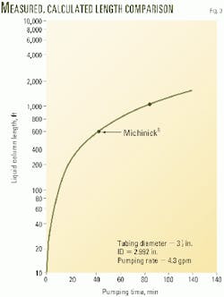
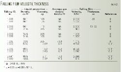
Fig. 3 shows the calculated values of Lc vs. tpump, and Table 1 compares the calculated values of Lc with two measured data points.8 The good agreement indicates that the simplifying assumption to neglect Qdrain in Equation 1 is justified.
During the pumping period, the drain-off column front is moving downward. Equation 3 gives its velocity, uCF. Table 1 shows that the calculated and measured values of column-front velocities are reasonably close.
When the injection pump is turned off, the liquid column may remain at the top of the tubing string, but its length is gradually reduced by the solution draining off at the bottom of the tubing.
Michinick reported that liquid column length decreases at its bottom at the rate of 120 fph, while the liquid film falls at 2,900 fph.8 On the other hand, the column may move downward slowly, depending on gas pressure in the tubing.
Patton reported that the liquid column moves downward at 190 fph, while the film is moving at 1,015 fph.9
Falling film velocity
Jackson and others measured the velocity of falling film in tubing that was in a surface facility or a laboratory by measuring the solution's volumetric flow rate at the end of the tubing.1 This is not possible in a well, however.
The leading-edge velocity of falling film in tubing is measured by timing the fall of liquid from the surface to a known depth.8-11 The liquid is mixed with a small amount of radioactive agent which can be detected with a sensor placed in the tubing string at a known depth.
Table 2 summarizes the measured velocity.
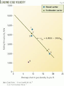
The data are plotted in a number of different ways, such as uLE vs. (pl - pg)R2/µl, uLE vs. (pl -pg)/ µl , and µLE vs. (pl - rg). The best plot appears to be uLE vs. pg (Fig. 4). The pg is the average gas density in the tubing.
Fig. 4 includes data from Jackson, Patton, and Kunefke.1 9 11 12 Michinick's data are not included because the gas density was not reported.8
The data points in Fig. 4 appear to suggest a linear equation (Equation 4) between the leading edge velocity and the average gas density.
This empirical equation is applicable to both water-based and oil-based corrosion inhibitor solutions. The falling film velocity in a surface facility or laboratory may not follow this equation.
Usually the pressure in the tubing is high; therefore, the gas density must be calculated using a gas compressibility chart, or an equation of state, such as the Redlich-Kwong equation or Peng-Robinson equation.12
Film thickness
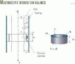
The flow of the falling film is laminar because its Reynolds number is less than 1,000. A microscopic momentum balance can be applied to a differential length of the falling film (Fig. 5) to obtain an equation of motion (Equation 5).
If the inhibitor solution is a Newtonian fluid, its shear stress is given by Equation 6.
Equation 7 is obtained by combining Equations 5 and 6. In Equation 7, u(r) is the local velocity of the liquid inside the film.
The average velocity of the falling film, or leading edge velocity, is the more important value in a batch treatment. Integration of Equation 7 yields the average velocity (Equation 8).
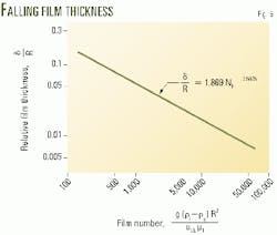
Equation 8 shows the relationship between the leading edge velocity and film thickness. Once the velocity is known, the relative film thickness can be obtained from this equation by an iterative numerical method or by a simple alternate solution that uses a dimensionless number, called the film number NF (Equation 9).
This equation is supported by Jackson's data, and therefore, means that Equations 7, 8, and 10 apply to the falling film in both short and long tubing.
Temperature
Formation temperature increases with depth and varies from location to location. In the Gulf Coast areas, such as Texas and Louisiana, the gradient can be as great as 1-2° F./100 ft of depth. This means that the falling film in a deep well is being heated by the formation.
Heat can change both film density and viscosity. When the well is shut in, formation temperature and the temperature of the falling film on the tubing wall can be considered equal because the film is thin. Equation 11 calculates the formation temperature, TE. In Equation 10, z is depth, and T0 is surface temperature at the wellhead.
Example problem
Equation 4 can be used to calculate the leading edge velocity, uLE, of the falling film in the production tubing. But because Equation 4 is an empirical equation, it could be improved by additional data, such as the effects of temperature and wall friction on the falling film velocity.
After calculating velocity with Equation 4, one can use Equations 9 to calculate the film number NF. Then, the film number can be used to obtain the film thickness with Equation 10 or Fig. 6.
Once the falling film velocity and film thickness are known, one can readily calculate the required shut-in time and the amount of corrosion inhibitor solution needed.
For example, assume a 2.992-in. tubing ID and an injection pump running for 42 min at 4.3 gpm. The first steps are to find the liquid column length at the end of the pumping, and then the column front velocity as follows:
The next steps are to find the leading edge velocity of falling film and the film thickness for a solution density and viscosity of 51.0 lbm/cu ft and 2.88 cp. The average density of the gas inside the shut-off well is 9.6 lbm/cu ft.
- From Equation 4, uLE = [6,459.6 - 246 (9.6)] = 4,098 fph.
- Equation 9, NF = [(4.169 x 10⁸) (51 - 9.6)(2.992/12)2]/[(4,098)(2.88 x 2.4191)] = 3.758 x 10⁴.
- When g = 4.169 x 10⁸ fph2 and applying NF to Equation 10, then d/R = 8.91x 10⁻³ and d = (8.91 x 10⁻³)2.992 = 26.7 x 10⁻³ in.
Acknowledgment
The suggestions and comments from C.F. Speed of Tuboscope Vector International are greatly appreciated.
References
- Jackson, M.L., "Liquid Films in Viscous Flow," AIChE Journal, Vol. 1, No. 2, 1955, pp. 231-40.
- Dukler, A.E., "Dynamics of Vertical Falling Film Systems," Chem. Eng. Prog., Vol. 55, No. 10, 1959, pp. 63-67.
- Drew, T.B., Hoopes, J.W. Jr., Vermeulen, T., and Cokelet, G.R., Advances in Chemical Engineering, Academic Press, New York, 1964.
- Ho, F.C.K. and Hummel, R.L,. "Average Velocity Distributions with in Falling Liquid Film," Chemical Engineering Science, Vol. 25, 1970, pp. 1225-37.
- Wilson, S.D.R., "Flow of a Liquid Film Down a Slightly Inclined Tube," AIChE Journal, Vol. 20, No. 2, 1974, pp. 408-10.
- Blass, E., "Gas/Film Flow in Tubes," International Chemical Engineering, Vol. 19, No. 2, April 1979, pp. 183-95.
- Churchill, S.W., Viscous Flows, Butterworths, Boston, 1988.
- Michnick, M.L., Annand, R.R., and Farquhar, G.B., "Batch Treatment of Gas Wells with Corrosion Inhibitors," Corrosion 71, Mar. 22-26, 1971, Chicago.
- Patton, C.C., Deemer, D.A., and Hilliard, H.M. Jr., "Oil well Liquid Inhibitor Effectiveness," Material Protection, April 1970, pp. 37-41.
- Kunefke, V.P., Exxon Co., 1975.
- Fang, C.S.. and C.F. Speed, "Corrosion Inhibitor Film in Batch Treatment of Gas Wells", Corrosion 90, Apr. 23-27, 1990, Las Vegas, Nev.
- Peng, D.Y. and Robinson, D.B., "A New Two-Constant Equation of State," Industrial Engineering and Chemistry Eng. Chem., Vol. 15, No. 1, 1975, pp. 56-64.
The author
Cheng-Shen Fang is professor of chemical engineering at the University of Louisiana, Lafayette. He holds a BS from the National Taiwan University, Taipei, and MS and PhD degrees from the University of Houston.
