Remediating UK river crossing addresses variety of concerns
To address the exposure by scour of Mainline Pipelines Ltd.'s high-pressure petroleum products line crossing the River Wye in the UK, design and remedial construction allowed for safety issues, the potential impact on the river ecology, recreational river users, the river hydrology, and restricted access to the steep northern riverbank.
Originally laid in 1972, the line moves products from the port at Milford Haven to the Midlands of England. Mainline Pipelines discovered the exposure early in 1999 and knew that a break in or temporary shutdown of the pipeline would have had serious consequences.
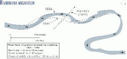
A review of historical air photographs and maps, dating from 1888, showed that the meandering channel of the River Wye has shifted to the north at an average rate of 0.65 m/year. Thus, the remedial works would have to account for ongoing vertical and lateral scour. And river-training works would be required at the site to ensure long-term protection of the pipeline.
The design consisted of filling the eroded riverbed and bank with rock aggregate and placing a protective layer of graded rock riprap. Grout-filled fabric formwork bags were placed beneath the pipeline to minimize deflection and development of unacceptable stresses in the exposed length during rock placement.
Rock-filled wire mattresses were placed immediately on top of the pipeline to protect it from point loading of the angular riprap. A satellite-guided positioning system was used to control material placement, and environmental monitoring of river water quality was carried out continuously during construction.
This article describes the investigation, assessment, design, and construction of remedial measures to extend the life of the pipeline.
Setting
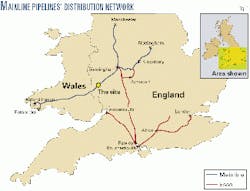
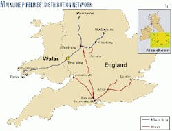
In the UK, the onshore distribution pipeline network includes a main petroleum line to deliver products from the west coast of Wales to Birmingham in the Midlands (Fig. 1). Owned by Mainline Pipelines, the line is operated by Esso Petroleum Co. Ltd. and is a multiproducts pipeline used by a number of UK petroleum companies.
It was constructed between 1972 and 1973, is 228 km (142 miles) long, has a nominal diameter of 400 mm (16 in.), and operates at a pressure of approximately 90 bar (1,300 psi). The line crosses terrain ranging from hills and mountains to flat plains. It has nine major river crossings and one booster station.
The line crosses the River Wye downstream of Hay-on-Wye, near the border with Wales. The crossing is on a meander bend in the river with a gravel shingle bank on the inside of the bend to the south and a steep earth bank 2-3 m high on the outside of the bend to the north. The river channel is set into a flood plain and the channel is approximately 40 m wide.
The pipeline is typically 0.9 m below the level of the flood plain, but as it approaches the river channel, bends take it deeper so that, at the time of construction, it passed a minimum of 0.9 m below the riverbed.
It was laid in a backfilled trench, and a concrete weight coating secured the section of pipeline beneath the river before placement. Where the pipeline passed beneath the steep northern bank, a headland of rockfill material with a stone facing was used to reinforce the bank against river erosion.
The original design life of 30 years was now required to be extended for an additional 30 years.
The River Wye flows continuously throughout the year and floods after heavy rainfall in the mountainous catchment area upstream of the river crossing. One flood in February 1999 caused significant erosion of the north bank immediately upstream of the crossing.
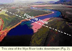
Part of the rock headland was outflanked and washed away during the flood (Fig. 2, left bank upstream of pipe). As the extent of the erosion threatened the integrity of the pipeline, Mainline Pipelines approached Golder Associates (UK) to help assess the extent of risk, the need for mitigation, and implementation of remedial measures.
The investigation included a topographic and hydrographic survey of the river crossing, visual inspection of the pipeline by divers, sampling and testing of riverbank and riverbed materials, testing of the cathodic protection of the pipeline, and aerial inspection and photography of the crossing.
The site survey, indicated that vertical scour of the riverbed had exposed and scoured the pipeline, leaving an unsupported span of 9 m at the time of the survey.
Testing of the cathodic protection showed that this was functioning correctly. It was not until late April 1999, however, that river flows had fallen adequately and water clarity had improved sufficiently to allow divers to inspect the pipeline.
Before this, the condition of the pipeline and the duration it had been exposed in the bed of the river, subjected to impact and abrasion, was unknown. Fortunately, the inspection only revealed one crack running along the exposed length of the topside of the concrete weight coating. Otherwise there was no observed damage.
A comprehensive understanding of the nature of the river crossing and condition of the pipeline was developed based on the survey, inspection, and initial analysis.
Short-term measures
With the information obtained, an assessment of the situation concluded remedial measures were required to ensure the integrity of the pipeline at the crossing and these should be carried out as rapidly as practically possible.
To expedite reinstating the integrity of the pipeline, it was decided to implement the remedial works in two stages:
- Measures that could be implemented rapidly, thereby providing protection in the short-term.
- Measures to provide longer term protection.
Following are the design objectives for the short-term remedial measures:
- Pipeline protection to ensure continued safe operation until implementation of the long-term remedial measures.
- Design and implementation of the short-term remedial measures within a period of weeks rather than months.
- Avoidance of measures that would raise the riverbed above the original 1972 elevation.
- Use of readily available local construction materials.
River hydrology
Except for some flood data for 1998, historical river-flow records were unavailable for the design of the short-term remedial measures. Anecdotal information, however, revealed that there had been several significant recent floods.
In 1960, flooding forced evacuation of the local community, and 1998 saw five significant floods. In October 1998, one of these resulted in the river level exceeding the capacity of the river flow-monitoring stations and a drowning at a farm upstream of the crossing.
Discussions with governmental authority whose responsibilities include river and river monitoring revealed that the October 1998 flood was the second most significant since 1935, after the 1960 event.
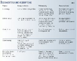
Based on the flow estimated by the agency for October 1998, a flow rate of 800 cu m/sec was selected for the design of the short-term remedial measures, which equates to the October 1998 peak flow plus 20%.
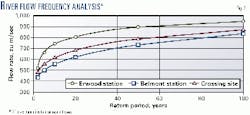
Subsequent to completion of the short-term measures, historical flow data for 1935-1998 were obtained for two flow-monitoring stations, one 35 km upstream of the crossing at Erwood and the other 34 km downstream at Belmont.
These data were analyzed with the program CFA (consolidated frequency analysis from Environment Canada, a governmental agency) to determine the long-term characteristics of the river flow at the site.
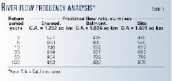
Table 1 and Fig. 3 show flows of various return periods based on the line of best fit. Flows at the site were predicted by linear interpolation between the two stations based on catchment areas.
The analysis of these data showed that the short-term design peak flow value of 800 cu m/sec has a return period of about 54 years.
Geomorphology; hydraulics
A geomorphic analysis used field data on the riverbed material and a series of historical air photographs and maps of the site. The photographs and maps covered1888-1984. The riverbed material is characterized by gravel with a D50 of 43 mm.
At the pipeline crossing, the River Wye is a meandering gravel-bed river with a shallow gradient. The river banks are gradually eroding on the outside and accreting on the inside of the river bends.
The analysis showed that the north bank of the meander at the pipeline crossing has been moving northeasterly at about 0.65 m/year since 1891 (Fig. 4). Similarly, the south bank has migrated at approximately 1.0 m/year. Thus, the river channel had narrowed to 45 m from 60 m at the crossing.
The desk study confirmed that lateral erosion at the crossing is a major issue and the likely cause for exposure of the pipeline. The river processes govern the design and longevity of any repair measures.
The river hydraulics of the River Wye were analyzed for design of the erosion control of the revetments.
The hydraulic analysis was based on 10 surveyed cross-sections of the river. These were entered in the one-dimensional hydrodynamic model HEC-RAS developed by the US Army Corps of Engineers.
This model was used to predict average velocities and water levels at each cross-section for various river flow rates. The model was calibrated with the water-level measurements collected during the site survey. An average cross-section velocity of 1.7 m/sec was selected for design since it was the maximum of the predicted average velocities at the cross-sections.
Since installation of the pipeline in 1972, the riverbed has been subjected to considerable change with lateral erosion at the north bank and vertical scour of the riverbed at the pipeline crossing and downstream of the crossing. The resulting pools are 5-6 m deep.
Vertical scour was estimated with regime theory, material characteristics, and the velocities calculated by the hydraulic analysis. The scour for the design 800 cu m/sec flow rate was estimated to be 2.5 m below the existing riverbed.
Design to protect against vertical scour usually uses one of two methods: excavating to the predicted scour depth and backfilling with rock or providing a "self-launching" toe apron. The latter method is easier to construct but requires a larger volume of material. A site-specific assessment of each method is required.
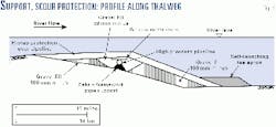
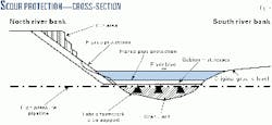
The philosophy of a self launching toe apron is to provide a wedge of rockfill that if undercut falls into the scoured riverbed providing "self-armoring" to the scoured hole. For the pipeline crossing of the River Wye, the self-launching toe apron method was found to be the most practical and economic (Fig. 7).
Lateral scour was to be controlled by armoring the north riverbank. A key objective for the design was to control both lateral and vertical scour.
Scour protection was provided by a 600-mm layer of graded riprap (D50 of 300 mm). The size of the riprap stone (D50) met the design flow condition, and the gradation was established with knowledge of available materials produced by blasting at a local quarry.
Concept development
Based on the understanding of site processes together with the stated design objectives, three design concepts for the short and long-term were developed:
- Install a new pipeline at the same location but buried deeper to avoid future lateral and vertical erosion.
- Install a new pipeline at a different location with appropriate burial depth.
- Construct a protection scheme for the existing pipeline.
Least impact on the river geomorphology could be achieved through burying a new pipeline deeper and allowing for future lateral erosion on the north bank of the river.
This option was not viable from an economic perspective, however, primarily due to the impact of shutting down the pipeline. The possibility of relocating the entire crossing was also discounted on cost. Thus, the third option was selected:
Bank-protection works at the site were to train the river and prevent further erosion of the north bank.
The short-term remedial design, therefore, consisted of the following components:
- Gravel base and riprap cover over the existing pipeline.
- A self-launching toe apron and bank protection to prevent future undermining of the rockfill cover and bank protection by vertical river scour.
- Bank protection on the north bank to prevent future lateral erosion.
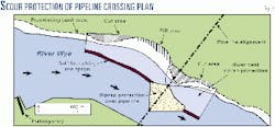
These components are illustrated in plan, profile, and cross-section Figs. 5, 6, and 7, respectively).
Design issues
The main design elements of the remedial design had been identified but, before construction could start, these needed to be tailored to address site-specific issues. These issues included:
- Working within the confines of a Site of Special Scientific Interest (SSSI) and Candidate Special Area of Conservation (cSAC), each a designation of English Nature related to wildlife habitat and geologic features or landforms.
- The potential for increasing sediment load within the river during construction because the spawning grounds of a rare species of shad had been identified 100 m downstream.
- Site layout for optimal material import, stockpiles, plant operation, and safe working.
- Consideration of recreational users of the river, such as canoeists and fishermen.
- Avoiding deflection, stressing, or point loading of the pipeline during rock placement.
In addition, an essential requirement was to maintain the operation of the pipeline. This introduced a number of specific issues, including:
- The potential for environmental pollution due to pipeline rupture during construction.
- General plant operation, control, and monitoring to protect the pipeline during construction.
Construction risk assessment
At the design stage, a risk-assessment in accordance with the Construction (Design and Management) Regulations 1994 (UK) assessed the options available to eliminate, reduce, or control any hazards identified and highlighted any residual risks.
The risk assessment identified that it would be impossible to eliminate the potential risk for pipeline rupture as a result of construction activities. Therefore, design measures and construction techniques needed to be adapted to manage and reduce the residual risks to an acceptable level.
The risks that needed to be managed were associated with pipe support, placing material under and over the pipeline, and construction operations close to the pipe alignment.
Pipe support and protection
Design of the backfill around the pipeline needed to address two issues; filling of the eroded riverbed beneath the pipe and placing scour protection above the pipe (Figs. 6 and 7). Backfill beneath the pipe was critical, as it was required to provide support to limit deflection and stressing of the pipe.
Options identified included hand placed granular backfill, piling to provide support in conjunction with granular backfill, and grout-inflated fabric formwork to provide support in conjunction with granular backfill.
Assessment of these options considered the potential for settlement of the in situ riverbed material, in addition to the behavior of the fill. The riverbed consisted of sand and fine-to-coarse gravel with low clay and silt content.
Long-term consolidation settlement was unlikely because of its particle size distribution and the depositional environment. The potential for settlement of the granular backfill material due to particle realignment and contact crushing was also of concern.
To minimize this risk and any resulting potential deflection and stressing of the pipeline, an alternative pipe support coupled with hand-placed rounded "single sized" granular fill was necessary, which would be less susceptible to particle realignment and contact crushing.
Piling would have provided rigid point supports but was discounted because of access and installation difficulties and potential cost. Grout-inflated fabric formwork techniques were selected because this technique offered numerous benefits.
The fabric formwork bags would be relatively straightforward and quick to install and inflate from the steep north riverbank, and land-based grouting equipment could be used remote from the river.
The bag configuration could provide a relatively uniform distributed support. Twin compartment bags would allow secondary grout injection to accommodate the potential for loss of support due to grout shrinkage or riverbed settlement.
Short-term measures
Construction work was carried out almost entirely from the north bank and from within the river and was completed in 5 weeks.
The main items included a crane with grab, a hydraulic-tracked excavator, and a dump truck for moving materials around the site. Rockfill materials were imported to the site by road.
Protection was placed around the pipeline from two rockfill platforms built out into the river. Protection to the riverbank was placed from the adjacent flood plain level.
Construction-control issues
Two major concerns were that filling operations were to be undertaken around a live pipeline within a river and that associated equipment would be operated close to the pipeline alignment.
The scoured riverbed profile made it necessary to undertake extensive filling operations both upstream and downstream of the pipeline alignment before the backfilling and support of the pipe could be undertaken.
To achieve a degree of operator visibility in this obscured environment and allow control of the associated risks, Mainline Pipelines and Golder employed Real Time Kinematic Global Positioning System ("RTKGPS") techniques.
With a Trimble 7400 RTKGPS system, a local base station was established. With a jib-mounted GPS antenna, a cabin-mounted computer with a high definition, high light-intensity screen, running Coastal Hypack software provided real time grab navigation information to the crane operator.
This allowed the operator to place material accurately and with confidence relative to the pipeline, via a survey background which included the pipeline alignment. It also provided daily records to monitor construction progress and control future activities by allowing zones requiring additional material to be identified on the cabin display.
Overall survey control was achieved by combining visual inspection by divers and the results of the RTKGPS with Single Beam Raythern Echosounder surveys and traditional optical survey techniques.
Pipe support, protection
Formwork bags positioned at quarter points of the unsupported span supported the pipeline. The technique, typically used offshore, had to be modified to prevent grout discharge into the river.
Nonreturn male and female couplings were fitted to all grout lines to accommodate the continuous inflation of the individual bags with connection and disconnection of live grout lines within the river by divers.
The potential for lifting the pipeline or splitting of the grout bag by over pressurizing was also assessed. Because accurate monitoring of the inline grout pressure was impossible, back analysis concentrated on evaluating an equivalent grout pressure head. This was identified as approximately 3 m with respect to lifting the pipeline.
To limit the grout-injection pressure, the grout return discharge was located as close to the river level as possible. Divers continually monitored the underwater grouting operation with communication and video links to the riverbank to ensure adequate bag inflation and full support of the pipe.
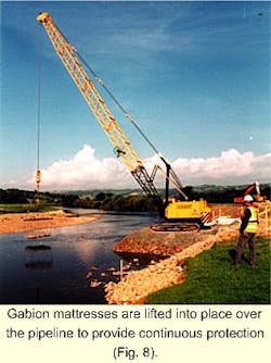
Protection against point loading from the riprap was achieved by placement of stone-filled gabion mattresses on a bed of fine granular fill cover to the top of the pipeline. The gabion mattresses were fabricated on the riverbank and lifted into place with a purpose made lifting frame (Fig. 8).
The mattress sizes were selected to suit the crane lifting capacity and its working radius and to aid diver maneuverability. The installed mattresses were laced together in situ to form a continuous blanket above the pipeline before placing the riprap stone protection.
Environmental issues
The SSSI designation to the River Wye applies to a land area 20 m either side of the riverbanks. As such all the activities were to be conducted within this area.
It was not possible to avoid disturbing the flora and fauna within this zone, and an approach of minimizing the potential disturbance and working area was adopted.
This was achieved by construction of a temporary access track parallel to but offset from the works river frontage and by managing the daily import of materials to remove the requirement for extensive stockpiles and associated land-take.
The reinstatement used approved grass seed mixes to encourage re-establishment of the original natural environment.
While no limits had been specified with respect to river sediment load, the impact of the works upon the river ecology was actively monitored. To reduce the potential for introduction of additional sediment to the river environment, the materials specification required that all imported materials be free from clay, organic, or other deleterious materials.
In addition, Partek turbidity meters with internal data loggers were installed upstream and downstream of the works. These units provided readings of turbidity at regular intervals throughout the works.
These readings provided a means of checking the relative sediment levels within the river so that, if required, procedures could be modified to reduce any detected influence. The monitoring showed that changes in the turbidity due to construction activities were negligible compared with natural changes in the river turbidity.
To manage the residual risk of the potential for pollution associated with rupture of the operating pipeline, emergency procedures were defined and implemented at the site. It was recognized that such an event would cause an environmental disaster and that containment of a resulting spill would be of paramount importance.
To address this issue, all site personnel were trained in deployment of spill containment and cleanup equipment that was retained at the site throughout the works. In addition, the emergency fire services' oil-spill response equipment was mobilized to the region.
Regular inspections are being carried out including hydrographic and visual surveys to ensure the crossing is performing as expected and contingency plans are in place for any maintenance.
Mainline Pipelines is currently preparing for implementation of the long-term remedial measures this spring.
Acknowledgment
The authors thank the following companies: Divemex Ltd., Longdin & Browning Ltd., SeaMark Systems Ltd., O & L Construction Ltd., P Trant Ltd., Ken's Tipper Hire and Nash Rocks Quarry Products, and Pipeline Management.
The authors
K. Bruce Dean is a senior river engineer with Golder Associates, based in Calgary. He is a registered professional engineer in the provinces of Alberta, British Columbia, Saskatchewan, Newfoundland, and Ontario and a member of both the Canadian and American Societies of Civil Engineering. He holds an MSc.
Femi Ade is a water resources engineer with Golder Associates based in Calgary. He holds a PhD (1966) from University of Alberta, Edmonton, and has more than 8 years of experience. He is a registered professional engineer in Alberta and a member of the Canadian Society of Civil Engineering.
Les Sawatsky is a senior water resources specialist with Golder Associates Ltd. based in Calgary and has more than 20 years' experience in hydrology and river engineering studies. He holds an MSc.
Richard Gray is the pipeline protection engineer for Esso Petroleum Co. Ltd. (UK) and Mainline Pipelines Ltd. He is an active member of the Pipeline Industries Guild and immediate past chairman of the Wales & Western Branch. Gray has been employed by Esso Petroleum Co. Ltd. for 32 years.
John Cutler is team leader for the contractors and consultants market sector in Golder Associates (UK) Ltd.; he joined the company in 1986. He holds a BSc (honors) and an MSc. Cutler is a chartered engineer and chartered geologist; fellow of the Geological Society; and a member of the Institution of Mining & Metallurgy, International Association of Engineering Geologist, British Tunneling Society, and British Geotechnical Society.
Neil Wheeler is senior civil and geotechnical engineer for Golder Associates (UK) Ltd. Previously, he was civil and geotechnical engineer for Golder Associates (1998-2000), geotechnical engineer for Scott Wilson Kirkpatrick & Co. Ltd. (1994-98), and graduate engineer for Applied Geology Ltd. (1992-94). He earned an MEng (honors; 1992) in civil engineering from the University of Newcastle Upon Tyne. He is a chartered engineer in the UK and a member of the Institution of Civil Engineers, UK.
Based on a presentation to the International Pipeline Conference (IPC2000), Oct. 1-5, 2000, Calgary.
