Hot tap installed on operating sour-gas line
In the winter 1999-2000, Chevron Canada Resources, Calgary, successfully completed a hot tap on the Simonette high-pressure sour gas transmission line near Grande Prairie, Alta.
The hot tap was required to bring new production into the Simonette pipeline without shutting in existing production. It was completed under full line pressure and gas-condensate flow with temperatures averaging -20° C.
The job demonstrated that such hot tapping on sour gas lines can be completed safely under proper procedures. In this hot tap, Chevron Canada had a technical advantage by having a section of the original pipe, all the line material test reports, and hydrogen-induced cracking (HIC) resistant steel.
Following are the minimum requirements for a similar hot tap:
- The pipe must have greater than 4.8 mm WT to prevent the risk of burn through.
- The carrier pipe must be corrosion and lamination free.
- The carbon equivalent (CE) of the pipeline material must be known.
- The weld procedure must be developed with a pipe of equal or greater CE with the same diameter and wall thickness.
- The procedure development must duplicate the worst-case quenching effects of the carried pipe fluid.
- Preplanning for emergency is critical to ensure the safety.
Design pressure of the 12-in., Grade 359 Cat II Simonette pipeline is 9,930 kPa and the line operates at 8,200 kPa. The gas in the main transmission line is approximately 2% H2Sand 4% CO2. The gas being brought on through the 4-in. hot tap tie-in was 21% H2Sand 5% CO2. At the tie-in point the transmission line temperature was 3° C.
Safely welding on the pipeline under these conditions posed a considerable technical challenge. In welding of sour service lines, it is critical that the final weld hardness be less than Vickers 248 microhardness. This can be very difficult to achieve during welding on a line transporting a quenching medium of gas and condensate. In addition, hydrogen charging of the steel from operation in sour service can lead to hydrogen embrittlement during welding.
Ludwig & Associates, Calgary, developed the hot-tap welding procedure and extensively tested it to ensure that suitable weld microhardness was achievable under pipeline operating conditions.
As part of the procedure development, the welder who would perform the hot tap was tested repeatedly until he could confidently and successfully complete the weld. During fieldwork, the welding was rigorously monitored to ensure procedural compliance, thereby minimizing the possibility of elevated hardness zones within the completed weldment.
Simonette service
The Simonette pipeline primarily transports Chevron Canada's Simonette oil battery dehydrated solution gas to the Kaybob South gas plant. The pipeline is also used to transport third-party dehydrated gas and condensate.
The typical average acid-gas component was 2% H2Sand 4% CO2 with the average production being 670,000 cu m/day of gas and 300 cu m/day of condensate.
In fall 1998, a third-party oil and gas company wished to tie-in a new sour gas well into the Simonette line. This well has an average acid-gas component of 21% H2S and 5% CO2, and an average production of 280,000 cu m/day of gas.
The desire to tie-in this new production without shutting in 2,000 cu m/day of oil and associate solution gas at Simonette led to an investigation of performing a hot tap under operating conditions.
There are considerable technical challenges in completing a hot tap on a sour-service pipeline. Although it is not uncommon to hot tap sweet-gas systems, a review of those procedures showed the final hardness achieved would be unacceptable in a sour system.
The key technical challenges are:
- Achieving a final weld in which all hardness is less than 248 HV500 during welding on a pipeline with a quenching medium of flowing gas and condensate.
- Preventing cracking due to hydrogen charging of the weld from in service interstitial hydrogen.
- Preventing burn through of the pipeline during welding.
Before committing to the hot tap, Chevron Canada had to be certain it was feasible to overcome the technical challenges and complete the work without risk to crews. Ludwig and Associates was contracted to develop the weld procedure, lab test the procedure, train the welder, and supervise the on site welding.
Developing the procedure
The Simonette pipeline was constructed of CSA Z245.1 323.9 mm (13 in.) OD x 11.3-mm WT Grade 359 Cat II HIC-resistant steel. The mill-test documentation for the original pipe and a joint of that pipe from the original construction were available for use in developing the weld procedure.
A critical aspect of the hot tap weld is the welding sequence. This must be carried out so that each pass adequately heat treats or tempers the previous pass. The final cap pass, both inside and out, must be made entirely on the previous weld metal and the branch connection pipe.
These final passes must not be welded onto the carrier pipe because the resulting heat-af fected zone (HAZ) may be untempered, re sulting in unacceptably high hardness. To ensure that the root pass is tempered, the procedure requires the root to be welded from inside the branch first. The first pass is applied to the ID of the stub-on.
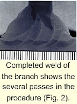
A second tempering pass is applied to overlap the first pass. It is important that the second pass not touch the base in-service material. (Figs. 1 and 2 show the bead sequence.)
The root can then be ground back from the outside of the fitting, making it easier to weld a defect-free root pass. This method can improve the quality of the root pass by reducing the chance of root-bead defects. A sharp-edged defect in a sour environment can result in stress that leads to stress corrosion cracking (SSC) failure even with acceptable levels of hardness.
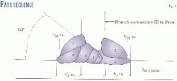
- Pass 1 (Fig. 1) is on the inside of the branch connection; two thirds of this pass is applied to the run pipe material.
- Pass 2 on the inside of the branch connection is welded completely on the first pass or the nozzle material. This will temper Pass 1.
- Pass 6, the second-to-last pass has two thirds of the weld applied to the parent material.
- Pass 7, the last pass on outside of the branch connection has 100 % of the weld on Pass 6 or the nozzle material.
It was fortunate that the actual pipe material to be used in the preparation of the procedure qualification record (PQR) was the same material used in the pipeline. This material had a relatively low carbon equivalent (CE), and it was anticipated, with some confidence, that acceptable procedure qualification would be able to be performed.
The time constraints associated with procedure qualification, however, required that all of the possible options associated with the coupon be explored in as few PQR preparations as possible.
It was expected that welding on the pipe, at the reported lower end temperature of 5° C. with flowing water as an internal quench medium, could produce unacceptably high HAZ hardness, even with the relatively low CE pipe material being used for the PQR.
For this reason, two procedure qualifications were conducted, each of which employed a different cooling medium.
The first PQR welding was conducted on a pressurized length of pipe containing a 50% ethylene glycol-water solution as the cooling medium. The choice of this medium was based on research, which indicated that cooling rates on the OD of a pressurized pipe containing this solution could be reduced relative to those cooling rates associated with flowing water.
An internal coupon pressure of 5.2 MPa was chosen to control OD cooling rate to a level higher than that expected on the pipeline by a comfortable margin but lower than that expected with flowing water as a cooling medium.
Even though preheat was to be administered to both the branch and run materials on the field weldment, preheating was only administered to the branch material during coupon welding. The decision was made to preheat the branch material to minimize the risk of PQR failure on the branch HAZ's due to the relatively high CE of the branch material.
The second PQR welding was conducted on the same coupon, but this testing was more conventional in employing flowing water as a cooling medium.
A second major difference between the welding conditions was that preheating was to be employed on both the branch and run materials during welding. This was found to be practical because of the relatively thick, 11.3-mm (0.450-in.) WT of the pipe material.
In the laboratory, a preheating temperature of 100° C. could be maintained on the branch material. Preheat of 100° C. was applied to the run material before each new electrode (each pass).
The results of hardness testing conducted on the PQR specimens produced from both quench media were found to fall below the maximum 22 HRC (248 HV500) recommended by NACE MR0175. The maximum average HAZ hardness levels were found to be higher on the 50% ethylene glycol-water coupon, but the actual hardness levels were found to be less scattered. This was probably due to the more varied run pipe-wall temperature during the course of welding of the continuously re-preheated water-filled coupon.
Table 1 presents a summary of the hardness test results.
Training of the welder
It is critical that the welder be educated in the correct technique before the hot tap.
Typically, welders are trained to produce defect-free welds and rarely consider weld hardness. The welder must weld with strict adherence to the procedure to attain the hardness levels required.
The welder was required to attend a training session to understand the technical aspects of the procedure. He was also tested on the same pipe size and orientation as that to be encountered on the hot tap and needed several attempts at the procedure successfully to achieve the desired weld quality.
Safety
The up-front technical work gave Chevron Canada the confidence that the hot tap could be safely preformed. The company also developed safety procedures to be followed to ensure that risk to the field staff was minimized.
The wall thickness and fracture properties of the pipe made for a very low risk of burn through or cracking to failure during welding.
The most significant risk of failure would be after the hot tap was completed. The most likely failure scenario would be a crack of the weld root after exposure to sour production with the result of a gas release around the reinforcing saddle.
A safety specialist was on site at all times during the procedure and an evacuation and emergency shutdown plan was in place. Before starting the welding operation, both Simonette and Kaybob South were informed and prepared to respond if required.
During the actual hot tap into the pipeline, the machine operator was masked and used breathing air apparatus, H2S detection was in place, and a rescue crew stood by.
Field welding
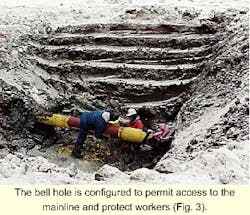
The pipeline had to be safely exposed and excavated. The bell hole used for access had to be properly prepared and sloped to ensure safety of the crews (Fig. 3).
At the hot tap location about the area to be welded, a complete ultrasonic testing (UT) grid was performed for 600 mm on either side of the weld area. The UT grid scan was used to ensure that no corrosion had occurred and that the wall thickness was uniform and to check for any measurable inclusions or laminations.
In addition to the UT, radiography was used to check the entire circumference of the area to be welded. This was done to ensure uniform wall thickness around the circumference of the pipe. The calculations for the attachment assumed that the pipe wall was in original design condition.
The results from the UT and radiography showed no corrosion nor laminations.
The hot tap location was on the up slope of a hill where condensate slugging would occur. To minimize the risk of a condensate slug increasing the quenching rate during welding, operators pigged the pipeline 4 hr before the hot tap.
Although procedure qualification on the glycol-water solution filled coupon did suggest that run-pipe preheat did not have to be depended upon to achieve acceptable hardness levels, a minimum base metal temperature of 100° C. was attained before welding.
A desire to increase the amount of heat available and reduce the effect of quenching by the surrounding pipe wall led to use of a stress-relieving unit. Coils were wrapped around the complete circumference of pipe next to the weld and the area below the weld. The stress-relief equipment was set up so as not to impair the welder's access to the weld area or emergency egress.
The circumferential temperature of the carrier pipe had to be less than 120° C., or CSA Z 662 required that the maximum operating pressure of the pipe would have to be reduced.
Before preheating for welding, checks of the pipe-wall temperature with an infrared heat-sensing gun at various times showed that the pipe-wall temperature was either 6-7° C. or 2-3° C. The lower temperatures were believed to corresponded to condensate slugs.
After the pig had passed, the temperature was found to be 7° C. However, condensate built up and slugging was again occurring within hours of the pig passing, resulting in temperatures of 2° C. before preheating for welding.
The stress reliever heating the adjacent area at 100° C. was also ineffective at increasing the pipe-wall temperature at the weld area. The quenching effect of the gas-condensate was greater than the heat conduction in the pipe walls.
A propane-heating torch could not maintain the required preheat temperature and an oxygen acetylene torch was used.
Preheating the pipe directly in front of each electrode ensured that the required preheats were maintained.
Experienced technical staff was on site to confirm strict adherence to the procedural details such as preheat, rod size, pass sequence, volt and amp settings, travel speed, and inter-pass temperatures.
If problems occurred during welding or if preheat could not be maintained, Chevron Canada was prepared to stop the work and shut in the pipeline.
Nondestructive examination (NDE) was used during welding to ensure that a weld could be produced with no defects that would jeopardize the final weld integrity.
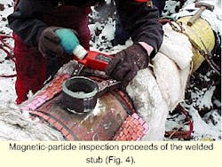
After completion of the inside weld and grinding to sound metal from the outside, the root pass of the weld was inspected with the dry-powder magnetic particle inspection (MPI) method to check for cracking (Fig. 4).
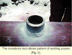
Immediately after the welding was completed, the weld was MPI-inspected for cracking. The weld was MPI-checked again 24 hr after the weld was completed to check for delayed hydrogen cold cracking (Fig. 5).
If cracking had been found on the weld metal or HAZ of the branch connection, the extent of cracking would have been reviewed and corrective action taken. If cracking had been found in the HAZ of the carrier pipe, the pipeline would have been shut down and depressurized.
If a crack or crack-like indication proved to be a shallow surface flaw, attempts may have been made to remove it by grinding. If this were successful, the pipeline could remain in service.
If the crack had extended into the carrier pipe material greater than 0.025 in. and could not be removed by light surface grinding, the pipeline would need to have been shut down, depressurized, and the welded section of pipe removed.
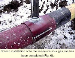
The reinforcement saddle was not welded to the carrier pipe wall. The reinforcement saddle is welded to the branch connection, and the weld area was then preheated to a minimum of 65° C. The completed weld of the reinforcement saddle to the branch connection was magnetic-particle inspected (Fig. 6).
When the welding and inspection were completed, an extension was welded on to the stub-on to allow the flanged connection and valve to be located aboveground.
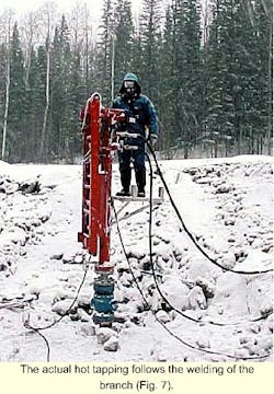
The connection was back filled and the hot tap completed (Fig. 7).
Acknowledgments
The authors acknowledge the following for their assistance in preparing this article: Frank Langenecker, Ludwig & Associates, Edmonton; Albert Van Roodselaar, Chevron Research and Technology, Richmond, Calif.; and Vic Lucs, Finlay Inspection, Edmonton.
The authors
Ray Goodfellow is currently a corrosion engineer with Chevron Canada Resources, Calgary. He holds a BSc (1990) in metallurgical engineering from the University of Albert and a diploma in welding engineering technology from the Southern Alberta Institute of Technology. Goodfellow also worked as a quality control manager for Nardies Fabrication and as welder for Canadian Pacific Railways.
Rory Belanger is engineering manager for Ludwig & Associates, Calgary. He has worked as a technologist for the City of Edmonton engineering department and a number of firms including Ball Engineering, Allan Nelson Engineering, and Dreco Energy Services in welding and metallurgical engineering. He obtained a BSc (1982) in the material engineering technology program from the Northern Alberta Institute of Technology and an MEng (1994) in welding engineering from the University of Alberta.
Based on a presentation to the International Pipeline Conference 2000, Oct. 1-5, 2000, Calgary.
