Rotary closed-loop drilling improves wellbore fluid flow
New, automated closed-loop steering devices are significantly reducing deviations from ideal wellpath in horizontal wells.
These devices immediately counteract deviations from the planned path through a downhole, closed-loop control of the directional drilling process. The reductions are from meters to fractions of meters. As a result, wellbore fluid flow efficiency is significantly enhanced.
Producing thin remaining columns of oil sandwiched between rising water and a highly mobile gas cap can be challenging.
It is crucial to minimize drawdown along the horizontal section to prevent coning and water cresting as most reservoirs are heterogeneous and kv:kh ratios are not constant.
The production of unwanted water or gas may be minimized by controlling the pressure differential between the heel and toe of the well.
With the recent advances in geosteering, it is possible to land a producing section virtually anywhere. However, it is sometimes difficult to maintain horizontal wells truly horizontal. Drilling with conventional steerable motors may cause a tortuous well path, as it is necessary to alternately rotate and slide the bottom hole assembly (BHA) to steer.
Multiphase flow modeling shows that pressure losses along the well path depends critically on the amplitude of the vertical component of these deviations.
The pressure head loss can be reduced by decreasing the angle of deviation. This modeling has been verified with production logging in highly deviated and horizontal wells.
Production logging clearly illustrates the various flow conditions encountered along a horizontal well and the problems associated with water holdup in sumps and gas slugging at very small uphill inclinations.
Examples of well profiles drilled with a recently introduced automated "closed loop steering-while-rotating" system now demonstrate the possibility to construct a production conduit that meets the requirements for minimum drawdown.
Minimizing drawdown
There are as many reasons to drill horizontal wells as there are ways to drill them. Whether the well is a complex multilateral or a simple horizontal well, it is often crucial to minimize the drawdown to mitigate or eliminate coning effects.
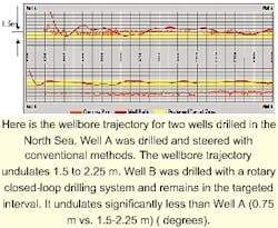
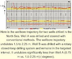
degrees shows the wellbore trajectories for two wells drilled in the North Sea. Both wells were drilled from the same platform. Drilling a 1,500-m horizontal section within a 1.5-m (5 ft) target interval was needed to produce the well efficiently.
Well A was drilled with a conventional geosteering assembly consisting of a steerable mud motor and a complete suite of MWD and formation-evaluation sensors. The formation-evaluation MWD included gamma ray, propagation resistivity, neutron porosity, and formation density.
The gamma ray was located about 12.2 m (40 ft) from the bit, and the directional measurements were about 25 m (83 ft) behind the bit. Considering that the directional measurement was 25 m behind the bit, the directional driller did an exceptional job of keeping the wellbore in the targeted interval.
When the bit exited from the targeted interval, however, the driller unavoidably over corrected, and the resulting wellpath deviated from the desired smooth wellpath.
This lengthened the total drilled interval, unnecessarily increased the tortuosity, and increased drilling time. Furthermore, additional drilling time was needed to stop and orient the motor and bring the well path back on target because of the required corrections.
The second well (Well B) was drilled with newer, rotary, closed-loop drilling technology (AutoTrak).1 A near-bit inclinometer provided inclination data during rotary drilling. The rotary drilling system downhole used the data to make adjustments to the drilling parameters while rotating, thus completely avoiding the need to stop and orient as with steerable motors.
In essence, the near-bit inclinometer allows the driller or the rotary closed-loop drilling system to steer from the front of the bus (as opposed to the rear of the bus) and, thus, better keep the wellbore in the targeted interval.
It is estimated that about 1 day of rig time was saved drilling the horizontal section on Well B just due to the decreased wellbore tortuosity and the ability to rotate while measuring wellbore inclination.
The decreased wellbore tortuosity also simplifies running the completion, and, as will be discussed later, the straighter horizontal wellbore promotes better wellbore fluid flow. Multiphase flow in undulating horizontal wells is extremely complicated.
Gravity segregation dominates the fluid distribution in the well and the fluid flow.
Heavier fluids will pool in local sumps, and light phase will accumulate in local attics. Heavier fluids (water or oil) flow along the bottom of the well, while the lighter phase (gas or oil) flow at the top of the well.
Sometimes, however, the flow regime is not simply stratified but is much more complicated.
The flow will be strongly time-dependent. In many horizontal wells producing two phases, slug flow will dominate and gas or light phase fluid pockets will push heavy-phase fluids.
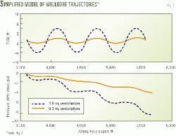
Fig. 2 shows a simplified model of the wellbore (undulations) observed in degrees and the wellbore pressure drop associated with the multiphase fluid flow. By reducing the wellbore undulations, the pressure head loss along the wellbore is halved. This would, of course, help minimize the tendency for a well to cone either water or gas.
Wellbore tortuosity
Any unwanted deviation from the optimum smooth well trajectory defines wellbore tortuosity. There are still different explanations, and up to now, no commonly agreed on definition of this phenomenon has emerged.
Wellbore tortuosity is a potential source of additional torque or drag and can lead to problems during drilling, running casing, liners, and completions. In horizontal and highly deviated wells, wellbore tortuosity can even impair productivity, especially the vertical deviations from horizontal.
Wellbore tortuosity includes not only deviations from an ideal, planned wellpath resulting from the directional drilling process, but also deviations from a smooth wellbore, which is directly caused by the design of the bottomhole assembly.
We refer to the total deviation (this includes both vertical and horizontal deviations) from the desired, smooth wellbore trajectory as "tortuosity" and the deviations which result in changes in the true vertical depth (TVD) as "wellbore undulations."
Deviations from the planned course and reasons for reduced smoothness of a borehole can be divided into the following categories:
- "Borehole spiraling" refers to boreholes that are generated with a screw-shaped inner wall. It will be created with any bottomhole assembly with or without a motor and regardless of whether a string rotation will be superimposed to a motor drilling assembly.
Spiraling can be avoided or at least reduced with a proper stabilization of the BHA and with a good radial guidance of the drillbit.
- Borehole diameter changes occur when a steerable motor with an integrated bend is being rotated for straight drilling. During the string rotation, the motor assembly rotates around an axis, which is defined by the position of the motor stabilizers in the borehole.
An offset from this axis is created at the bit because of the motor bend. This results in the cutting of an oversized hole.
Entering this oversized hole with the lowermost and later the uppermost stabilizer causes the assembly to find a new rotation axis with the result of drilling a smaller hole size.
Rotation of a bent steerable motor, therefore, creates a borehole with a constantly changing hole diameter between the bit size and the bit size plus two times the bit offset.
- Deviations created through the directional drilling process result from intended changes of the borehole course. With steerable motors, these deviations occur with every transition from the directional mode (sliding the assembly without string rotation), to the straight drilling mode (superimposed string rotation), and vice versa.
With automated "closed loop steering-while-rotating" drilling systems, the changes occur intentionally when changing the course and without intention in the automated mode, for example, in the mode to keep inclination on a predetermined value.
The macro-deviations caused by the directional drilling process are significantly smaller with automated rotary closed-loop drilling systems as compared to the deviations introduced with steerable motors. This is because steerable motors drill compound curves with straight and curved sections when motor bends are used to achieve large directional changes.
In contrast to this process, automated closed loop steering-while-rotating systems apply only the force to the bit that is required to change the drilling course. The measurement of the relevant directional parameters inclination and azimuth at or near the bit provides the earliest possible knowledge about magnitude and success of the directional drilling process, thus minimizing the borehole deviations.
The deviation caused by the control process itself is unwanted with steering-while-rotating systems. It is unlikely that the inclination of a course, for example, will be kept perfectly on the desired value.
A drifting of the inclination will cause the activation of the system at a certain threshold and a slight overshooting when passing the correct inclination angle. Therefore, the true course will permanently oscillate very slightly (typically by ±0.1 degrees) around the planned course.
- Multiphase flow in horizontal and nearly horizontal wells is extremely complicated. Flow patterns and fluid distributions change in both time and space.
In vertical wells, the flow regime is governed by the inflow profile and only changes when additional fluids flow into the well. In horizontal wells, the flow regime strongly depends on the wellbore inclination.
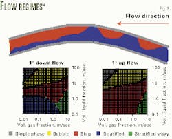
If we consider a simple but typical situation for multiphase flow in a horizontal well with a significant difference in fluid density (~0.5 g/cu m) between two phases, the flow will be stratified when flowing downhill and slugging when flowing uphill.
The flow regime changes from slug flow for slight uphill flow to stratified flow for slight downhill flow (Fig. 3). Such changes in flow regime take place for wellbore deviations as small as 1 degees.
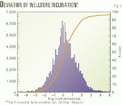
Spek and Veran presented wellbore deviation data for 150 wells from a thin oil rim field in West Africa.2 The bell-shaped histogram (Fig. 4) indicates that 66% of the deviations fall within ±1 degrees of horizontal for their wells.
Flow model description
Mechanistic, multiphase-flow models were used to study the effects of undulations on the along-wellbore pressure drop. These models were originally developed for modeling fully developed flow in pipelines and wells.
The models are similar to those used throughout the industry,3 4 but they have been tuned based on Shell flow loop and well data. Spek and Veran used these models to interpret production-log data in horizontal wells.2 More-detailed descriptions of the models can be found in papers by Oliemans,5 Wu,6 and Pots.7
The wellbore inclination angle along the well is calculated according to the formulation for average angle change (AAC), assuming a sine-wave trajectory. Then, it was assumed that the inflow is uniform along the wellbore.
There is no axial flow at the toe of the well. At the heel of the well, the axial flow equals the total production.
For these simulations, according to the model predictions, the downward flow is usually stratified and the upward flow is usually intermittent flow. We use the stratified flow model and the slug flow model described by Oliemans5 for these flow simulations.
The simulation results from the multiphase flow model given the hydrostatic and frictional pressure drop for fully developed multiphase flow. This is a simplification for real flows that tends to underestimate the influence of wellbore tortuosity and undulation on the along-wellbore pressure drop.
We believe, however, that our calculations still illustrate the dominant effect of the wellbore undulations (e.g., vertical deviations as measured by the AAC), on the along-wellbore pressure loss.
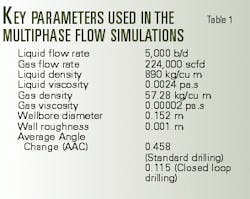
Table 1 summarizes the flow conditions used in our simulations. Two values of AAC were used: for the larger undulations 3 m (10 ft), typical of wells drilled without near-bit inclinometers and closed-loop steering, and 1.5 m (5 ft) for the smaller undulations associated with newer closed-loop rotary drilling systems.
Results
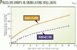
Figs. 5 and 6 summarize the main results. Fig. 5 shows how the along-wellbore pressure drop increases as the gas-liquid ratio increases. For all nonzero gas fractions, the pressure drop is much greater than that for a truly horizontal well.
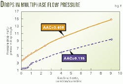
Fig. 6 shows the relationship between along-wellbore ratio of the pressure-drop for the multiphase flow and the pressure drop experienced by single-phase flow for different gas-liquid ratios.
The major difference between single-phase flow in undulating wellbores and multiphase flow in undulated wellbores is that multiphase flow suffers a higher pressure drop.
The higher pressure drop in multiphase flow is caused by the flow-pattern changes. In the downhill section of an undulated wellbore, the flow pattern is usually stratified, and the denser phase tends to accelerate. The faster the fluid moves, the higher the pressure losses due to friction.
Several things have been found:
- The major factor that contributes to the pressure drop in a horizontal well is the wellbore undulation severity or Average Angle Change (AAC).
- The pressure drop varies almost linearly with the value of AAC. A three to four times increase in AAC results in a three to fourfold increase in pressure drop.
- The major contribution to the pressure drop arises from the uphill flow hydrostatic component.
- The presence of liquid in a gas well or the presence of gas in a liquid-producing well significantly increases the pressure drop in high AAC horizontal wells.
- New drilling technology (near-bit inclination and rotary closed-loop drilling) can significantly reduce wellbore tortuosity and undulations.
As long as a horizontal well is producing only a single phase, drawdown will be distributed uniformly along the well. Once a horizontal well starts to produce a second phase, however, the along-wellbore pressure drops may increase dramatically. Increased pressure drops may limit the effective length of the well and increase coning or water cresting. During planning of a horizontal well, the drilling method should also be considered since it influences not only the economics of drilling the well but also the performance of the well.
Acknowledgments
The authors acknowledge many helpful Baker Hughes colleagues, and in particular, the work of Peter Weijermans and discussion with Jaedong Lee. We also thank Karen Bush for assistance with the manuscript preparation. Finally, we thank Baker Hughes for permission to publish this work.
References
- Donati, F., Oppelt, J., Tampini, Alessandro, Pagnitz, D., "Innovative Rotary Closed Loop System-Engineering Concept Proved by Extensive Field Application in the Adriatic Sea," IADC/SPE 39328 presented at the 1998 IADC/SPE Drilling Conference, Dallas, Mar. 3-6, 1998.
- Van der Spek, Alex, and Veran, Yves, "Horizontal Well Production Log Evaluation in Multiphase Flow," Proc., ETCE/OMAE2000 Joint Conference: Energy for the New Millennium, New Orleans, Feb. 14-17, 2000.
- Brill, J.P., and Mukherjee, H., "Multiphase Flow in Wells," SPE Monograph, Richardson, Tex. (1999) 17.
- Brill, J.P., and Beggs, H.D., Two Phase Flow in Pipes, Sixth Edition, January 1991.
- Oliemans, R.V.A., "Modeling of Gas/Condensate Flow in Horizontal and Inclined Pipes," paper PL240, ETCE Conference, Dallas, 1987.
- Wu, H.L., Pots, B.F.M., Hollenberg, J.F., and Meerhoff, R., "Flow Pattern Transitions in Two-Phase Gas/Condensate Flow at High Pressures in a 8 inch Horizontal Pipe," Proc., 3rd International Conference of Multiphase Flow, The Hague, The Netherlands, May 18-20, 1987, pp. 13-21
- Pots, B.F.M., Oliemans, R.V.A., and Tropé, N., "Modeling of Annular Dispersed Two-Phase Flow in Vertical Pipes," International Journal of Multiphase Flow, 1986, 12, pp. 713-32.
- Georgi, D.T., Wang, J., and Kröger, V., "The Benefits of Truly Horizontal Wells," SPE/PS-CIM 65526, SPE/PS-CIM International Conference on Horizontal Well Technology, Calgary, Nov. 6-8, 2000.
The authors
Dan Georgi is director of science and manager of the NMR program at Baker Atlas. Prior to his present position, he managed research at Core Laboratories. He holds a PhD from Columbia University and has worked at Woods Oceanographic, Exxon Production Research Co., and Esso Resources Canada (now Imperial Oil).
Jianrong Wang is a research scientist at Baker Atlas/INTEQ Houston Technology Center. He received his BS (1983) and MS (1991) degrees from the University of Petroleum, China, and a PhD (1997) from the University of Tulsa, all in mechanical engineering.
Volker Krueger is director of strategic technology development for Baker Hughes INTEQ in Houston. Before joining Christensen, one of the predecessor companies of Baker Hughes INTEQ, Krueger worked as a development engineer with FAG Kugelfischer and as a research engineer with the German Institute of Petroleum Research. Krueger holds a master's degree and a doctorate in mechanical engineering from the University of Hannover, Germany.
Based on a presentation at the 2000 SPE/Petroleum Society of CIM International Conference on Horizontal Well Technology, Calgary, Nov. 6-8, 2000.
