Database reflects recent trends in European gas-pipeline failures
Creation of an extensive pipeline-incident database has helped designers improve safety in Europe's gas pipelines.
In 1982, six European gas-transmission-system operators began gathering data on the unintentional release of gas along their pipeline transmission systems.
This project was formalized by the establishment of the European Gas Pipeline Incident Data Group (EGIG.) The purpose was to provide a broad basis for statistical use, giving a more-realistic picture of the frequencies and probabilities of incidents than would be possible if the independent data of each company were considered separately.
Collection of safety-related data has grown in significance as a result of increasing interest shown by local, national, and international authorities responsible for safe gas transmission.
In 1998, all the major gas transmission system operators in Western Europe were participating. The nine participating companies were:
- Dansk Gasteknisk Center AS, represented by Dansk Olie Gasproduktion AS.
- Enagas SA.
- Gaz de France.
- NV Nederlandse Gasunie.
- Ruhrgas AG.
- SA Distrigaz.
- SNAM SpA.
- Swissgas.
- Transco (part of BG), represented by BG Technology.
Considering the number of participants, the extent of the pipeline systems, and the exposure period involved (beginning in 1970 for most of the companies), the EGIG database is a valuable and reliable source of information.
The regional differences are not taken into account, so that the result of the database presents an average of all participating companies. Uniform definitions have been used consistently over the entire period. Consequently, the database gives useful information about trends that have developed over the years.
This article explains how the database was developed and shows the results of some analyses. Accumulated frequencies are given over the entire period.
As the exposure time over the pipeline system increases, each new year added has a smaller effect on the accumulated frequencies. Therefore, occasionally a separate presentation of the most-recent period is also given. This has been done by using the 5 years' moving average or by comparison of only the past 5 years with the accumulated frequency.
Damage classification
The criteria for the incidents in the database are:
- There is always an unintentional release of gas.
- The incidents are always related to an onshore gas transmission steel pipeline (this does not include production lines).
- There is a design pressure greater than 15 bar.
- Incidents are outside the fences of installations.
- The incidents exclude associated equipment (e.g., valves, compressors) or parts other than the pipeline itself.
Damages are recorded in the following three types, depending on the leak size:
- Pinhole/crack: Diameter of equal or less than 2 cm.
- Holes: Diameter of defect more than 2 cm and equal or less than the diameter of the pipe.
- Ruptures: Diameter of defect more than the pipe diameter.
Incidents are divided according to the initial cause into the following types:
- External interference.
- Corrosion.
- Construction defect or material failure.
- Hot tap made by error.
- Ground movement.
- Other and unknown causes.
The following information is recorded, depending on the type of the incident (only to explain possible differences in performances):
For external interference:
- Activity causing the incident (e.g., digging, piling, ground works).
- Equipment causing the incident (e.g., anchor, bulldozer, excavator, plough).
- Installed protective measures (e.g., slabbing, casing, sleeves).
For corrosion:
- Location (external, internal, or unknown).
- Corrosion type (galvanic, pitting, stress corrosion cracking (unknown).
For construction defect or material failure:
- Type of defect (construction or material).
- Defect specification (hardspot, lamination, material, fieldweld, unknown).
- Pipeline type (straight, field bend, factory bend).
For ground movement or other or unknown causes:
- Type of ground movement (dike break, erosion, flood, landslide, mining, river, unknown).
- Predefined subcauses (e.g., design error, erosion, lightning, maintenance, other weld, repair clamp, other/unknown).
For all incidents other information is also recorded, for example:
- Depth of cover.
- Size of leak.
- Type of leak (pinhole-crack, hole, rupture, unknown).
- Ignition (yes/no).
- Explosion (yes/no).
The failure frequency is calculated by dividing the number of incidents by the kilometer-years, i.e., the exposed length for the pipeline category under consideration and its exposure duration. All the frequency figures are given per 1,000 kilometer-years (km-yr).
Database content
The total length of the pipeline system of all the participating companies is still increasing. In 1998, the length was 109,188 km, and in 1997 it was 106,000 km.
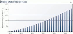
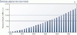
The total exposure in the 1970-1998 period was 2.09 million km-yr. Fig. 1 shows the development of the database from 1970 to 1998.
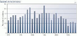
The total number of incidents in the EGIG database up to the end of 1998 is exactly 1,000. Fig. 2 shows the annual number of incidents in the database.
Table 1 gives the development of overall incident frequency.
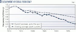
Fig. 3 gives an overview of the development of the overall average failure frequency over the total period 1970-1998. Shown is the gradual reduction in the incident frequency in each year as the cumulative total from 1970 onwards.
In order to see the results over the last period, without the influence of the past, the moving average is calculated only over the past 5 years (1970-1974, 1971-1975, 1972-1976, etc.). Fig. 3 also gives these results.
The main conclusions of the development are:
- The average failure frequency over 1970-1998 was 0.480/year/1,000 km pipeline with a 95% confidence interval of plus or minus 0.03.
- The failure rate has decreased by a factor 5 over the past 29 years.
Incident frequency; causes
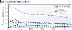
Fig. 4 gives the frequency per type of incident (main causes).
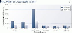
Fig. 5 shows the frequency per type of incident (initiating cause) over the total period (1970-1998) and the performance over only the last 5 years (1994-1998). The figures for 1994-1998 relate to that particular period (not cumulatively from 1970 onwards, as given in Fig. 4).
External interference remains the main cause of incidents with gas leakage: an average of 0.280 incidents/1,000 km-yr over 1970-1998. An improvement in incident frequency has been observed in recent years, however: 0.087 incidents/1,000 km-yr over 1994-1998.
An analysis to examine whether aging can be demonstrated led to the following conclusions:
- For the possible age-related failure causes (corrosion and material defects or construction failures) no aging could be demonstrated.
- The observed failure frequencies for pipelines constructed before 1964 are significantly higher than pipelines constructed after 1964.
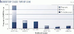
Fig. 6 gives an overview of the incident frequencies by cause and type of leak in the period 1970-1998.
The graph indicates that when a pipeline is damaged by external interference, there is a higher probability for getting a hole than for a pinhole crack or a rupture.
For external interference, the most dangerous activities are digging by excavators (42%) followed by ground works carried out by drainage machines and plows (9%), and public works using bulldozers and shovels (8%).
The most significant type of leak for construction defects and material failures and corrosion is a pinhole-crack.
External interference; corrosion
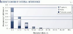
Figs. 4 and 5 indicate that external interference remains the main cause for gas leakage incidents. In Fig. 7, the frequencies caused by external interference are given per diameter class and type of leak.
This figure prompts the conclusion that there is a positive relationship between the diameter class and external interferences. There is no direct relationship, but the main factors that may influence the relationship are:
- Smaller-diameter pipelines are more exposed to external interference.
- Smaller-diameter pipelines can be easily hooked during ground works.
- Small-diameter pipelines have in general less wall thickness than large diameter pipelines (Fig. 8).
- Small-diameter pipelines have in general a lower grade of material than large-diameter pipelines.
It is anticipated that there is a direct positive relationship between pipeline incidents with gas leakage caused by third-party interference (outside forces on the pipeline) and the wall thickness. In Fig. 8, the frequencies caused by external interference are given per wall thickness and type of leak.
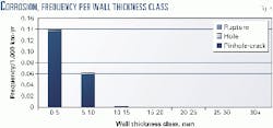
Corrosion is the third highest cause of gas leakage and occurs mainly in thin-walled pipelines (less than 10 mm). Fig. 8 shows the distribution. The frequencies for wall thickness classes up to 5 and 5-10 mm are caused by 8 and 7%, respectively, of all incidents and have an exposure of 11 and 28%, respectively, of the total exposure.
This figure prompts the conclusion that no corrosion incidents were observed on pipelines with wall thicknesses of more than 15 mm.
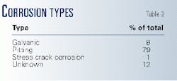
Of all corrosion incidents, 77% were external corrosion, 19% internal corrosion, and 4% unknown. External corrosion is subdivided into the types of corrosion listed in Table 2.
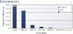
Pitting is the major contributor in external corrosion. Internal corrosion was not due to natural gas, as all the incidents with internal corrosion (19%) are caused by manufactured gas. Fig. 9 gives the frequency caused by corrosion by year of construction and type of leak.
An incident caused by corrosion will normally result in a pinhole. There was one corrosion incident observed by the EGIG members, however, that resulted in a rupture of the pipeline.
The pipeline was constructed before 1954, the material was Grade A, and the diameter was between 6 and 10 in. The type of corrosion was unknown for this incident, and the fractured length was some meters.
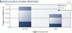
As expected, a greater depth of cover will reduce the occurrence of external interference faults. The variation with the depth of cover is given in Fig. 10.
Incident detection; injuries
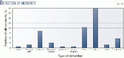
About 40% of all incidents in the EGIG database are detected by the public. The second highest "detector" is patrol surveys, and the third is the contractors.
Fig. 11 gives a complete overview.
On average, 3.8% of all the incidents result in an ignition. This is in the same order of magnitude as reported in EGIG over the years 1970-1997 (which was 3.9%).
The ignition probability is related to the type of leak classification: pinhole-crack, 3.4%; hole, 1.7%; rupture equal to or less than 16 in., 10.5%; and rupture of greater than 16 in., 28.6%.
From 1970 to 1998, no incident on a natural gas transmission pipeline caused fatalities or injuries on inhabitants (or residents).
The author
Rijnhold Bolt, since 1989, has been project manager and senior advisor for reliability engineering for Gasunie's gas transmission department. He has also served as a project manager in the research department (1978-1983) and a project manager and reliability engineer in the maintenance and operations department (1983-1989). He holds a BSc (1978) from the Technical College, Groningen, The Netherlands. Since 1990, he has served as chairman of a CEN (European Committee for Standar dization) working group to set up a single European standard for maintenance and operation of gas trans mission pipelines. Since 1992, he has been a member of the Reliability Information Exchange, which consists of six European gas transmission companies. And since 1992, he has been a member of the ISO working group on an international standard for maintenance and operation of all trans mission pipeline systems.
