Mudlogging method calculates coalbed gas content
Case studies show that gas-content calculations, as determined by a novel mudlogging technique, closely coincide with information derived through whole core desorption techniques.
Thus, this approach can provide an alternative and near-instantaneous method for evaluating single or multiple coal seams without the costly and time-consuming need to pull whole cores and directly measure desorbed gas volumes.
Theory
The approach described in this article, the last of a three-part series on novel mudlogging technologies, has been used in the San Juan, Raton, San Wash, and Powder River basins to overcome problems associated with missed core points, poor core recovery, lengthy trip times, and measurement uncertainty.
Yet similar to sealed-canister measurement techniques, this logging method also depends on basic desorption principles where rock cuttings are viewed as very small whole cores. In the case of rock cuttings, however, the drill bit crushes, grinds, or shears rock cuttings into small pieces, allowing extremely large surface areas and permeability boundaries.
Consequently, it can be demonstrated that most, if not all, coalbed gas is liberated into the mud stream before the mud column circulates to surface.
The process for calculating coalbed gas content involves the following steps:
- Calculate rock-cutting height. This calculation, which is not used directly in the gas content computations, determines whether the cuttings are indeed small enough to desorb most of the gas before reaching the surface.
Drill-bit cutter geometry, rotational speed, and penetration rate are used to determine rock-cutting height.
- Calculate hole volume.
- Calculate amount of gas liberated in standard cubic feet from hole volume.
- Calculate the weight in tons of the hole volume.
- Divide the amount of gas liberated by hole volume.
Thus, determining desorption rate/distance, along with cutting height, can allow coalbed gas content to be quantified.
Rock cutting height
The following formula can be used to determine rock-cutting height:
CH = 12.0 /(PR * ROT * CUT)
where:
CH = Drill bit cutter height, in.
PR = Penetration rate, min/ft
ROT = Bit rotation, rpm
CUT = Number of cutters impinging/revolution, cutters/revolution
For example, if PR = 0.5, ROT = 80, and CUT = 3, the drill cutting height is 0.10 in. This simple formula forms a first-order estimation of the process with drill-cutting height verified through sieve analysis.1 2
Respectively, the cutting width and length are deemed indeterminate in this analysis in that these dimensions are typically less than the height dimension. Prior workers indicate that about 80% of drill cuttings are less than 0.04-in. diameter.
Fruitland coal
For purposes of validity, it must be demonstrated that rock cuttings desorb most of their gas content before reaching the gas trap at surface. The following data, taken from a 1-ft long, 4-in. OD Fruitland coal core sample (La Plata County, Colo.), provides insights into the determination of desorption velocity, or the speed at which desorbed gas travels to the outer surface of the coal cutting.3
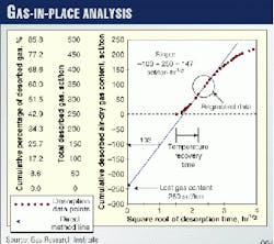
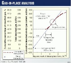
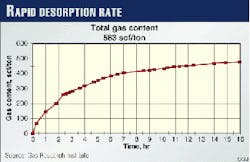
Desorption data are often analyzed in graphical form in which time, or the square root of time, is plotted on the x-axis, and cumulative desorbed gas is presented on the y-axis (Figs. 1 and 2).
In this case, gas content is presented as total cumulative gas content, while time zero depicts the desorption starting point. It can be seen that coals typically begin to desorb rapidly and then reach an asymptote.
For example, the core in Fig. 2 desorbed 250 scf/ton over the first 2 hr but only 150 scf/ton over the next 5 hr. Thus, out of a total of 583 scf/ton, 80% of the coalbed gas desorbed in the first 16 hr.
For calculation purposes, data taken from the 16-hr desorption point should be used in subsequent work, mainly because 70-100% of the desorption process takes place within this time period. This has been verified through studies conducted by the Gas Research Institute.
Altogether, the calculation of total gas content for this core sample, conducted through direct measurements, required 3 months.
Cutting size comparison
To gain a relative perspective on the rate of desorption for rock cuttings, it is necessary to compare the size differential between larger core samples and smaller rock cuttings.
If it can be assumed that the desorption rate remains directly proportional to the length of travel, then the radius of a 4-in. diameter core is 40 times larger than the radius of a 0.1-in. diameter drill cutting.
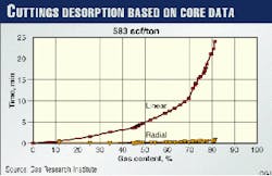
Therefore, a rock cutting will take 1/40th of the time to desorb 80% of its gas content, or 24 min (Fig. 3). This is typically within the time frame of many bottoms-up circulation rates.
Most likely, core desorption rates, proceeding over the distances pertinent to this discussion, simulate linear rather than radial relationships where the former desorbs at a slower rate than the latter. In this example, 50% of the rock-cuttings gas will desorb in 6 min, while a total of 70-80% of the gas will desorb in 20 min.
Thus, if the driller encounters coal seams between 1,000 and 2,000 ft, with circulation rates set at 1-2 min/100 ft, then it will take 10 to 40 min to circulate up the samples.
If the rock cuttings become smaller, because of natural fractures, lack of cohesion, water sensitivity, water solubility, or annular abrasion, then the gas desorption rate will increase within the time frame of interest.
In many cases, offset desorption data from analogous coal seams can be used to determine the rate of desorption.
Weight and volume
To calculate coalbed gas content with the mudlogging method, coal weight and gas volume must be determined. Thus, to determine coalbed gas content, the volume and weight of coal drilled/min and the amount of gas liberated/min from that volume must be calculated.
To determine the volume of coal drilled/min, the bit face area is divided by the penetration rate. The weight in tons of that volume is then determined through the measurement of coal density, obtained from density logs or offset data.
Next, the amount of gas can be determined by relating the size of the mudlogging show to the volume of methane gas in standard cubic feet. To measure this relationship, wellsite personnel must determine the mudlogging unit's response to both methane and acetylene over a wide range of gas concentrations.
Next, they must relate the size of the methane gas show in units to the methane gas volume by a calibration process that involves gas readings and carbide lags. Alternatively, a gas referencing system can be used where a known amount of acetylene or propylene is continuously pumped downhole.
As this continuous lag of acetylene or propylene returns to the surface, the methane gas show/units of acetylene can be determined.4
Because a functional relationship exists between the mudlogging unit and the gas trap's response to acetylene and methane, the rate of coalbed gas liberation can then be calculated in standard cubic feet/minute.
Thus, coal weight and the amount of gas liberated/drilled volume become known, allowing for the computation of combustible gas content in standard cubic feet/ton. If the mudlogging unit also measures carbon dioxide, nitrogen, hydrogen sulfide, and other noncombustible gases, these can be added to the combustible gas content of the coal.
Wyoming well
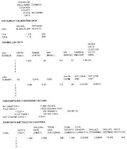
Data from a well in the Powder River basin compare favorably with offset whole-core canister data from a well in the Powder River basin (see accompanying box). Using real-time information, mudlogging personnel can determine all the necessary information for the computations except coal density, provided that the acetylene and methane responses are calibrated and that the gas-trap sensitivity is defined.
Instrument calibrations must be performed with varying mole percents of both methane and acetylene where the range of calibration should remain in the range of anticipated results.
Generally, catalytic bead-type sensors are twice as sensitive to the same volume of acetylene as is methane. This relationship, however, must be determined experimentally. Thus, instrument calibration and carbide lag data form the basis for this method.
For example, the data depicted in the box present a single calibration point where twice as much methane in relation to acetylene was required to give the same mudlogging instrument response. The instrument response and the carbide lag data clearly established a relationship between methane gas and instrument response.
Once the instrument was calibrated, the mudlogger determined the acetylene lag response with calcium carbide. Important information can be gathered from calcium carbide if wellsite personnel measure the amount before it is pumped down the drillstring.
As the box and Fig. 4 show, during a connection at 1,202 ft, 4 oz of calcium carbide gave a peak response of 45 units. If calcium carbide lags are used to determine coalbed-gas content instead of the gas referencing method, then the standard cubic feet of acetylene/ounce of calcium carbide must be determined through field testing.
This relationship is shown in the box under "Constants and conversion factors." In this example, 0.05111 scf of methane was present for every unit of mudlogging instrument response.
Now that the mudlogger has established a relationship between the amount of methane and the mudlogging instrument's response, the amount of methane gas for any drilled coal can be determined. For example, Fig. 9 indicates that the driller encountered a 6-ft thick coal seam at 1,348 ft. The penetration rate accordingly reached 2.5 min/ft with a 300-unit mudlog show.
Other pertinent information included a hole size of 17.5 in. and coal density of 1.7 g/cc. Thus, by multiplying the 300-unit mudlog show by the conversion factor of 0.05111 scf CH4/unit, it can be shown that 15.3 scf/min of methane gas was liberated.
The volume in cubic feet of coal/minute can then be determined by dividing the hole area in square feet by the drilling rate in minutes per foot. Next, the coal density in grams per cubic centimeter can be converted to tons per cubic foot.
If the coal density in tons per cubic foot is multiplied by the cubic foot of coal drilled per minute, then both the standard cubic feet per minute of liberated methane gas and the tons per minute of coal drilled become known.
Dividing 15.3 scf/min by 0.03545 tonnes/min then yields a gas content of 432 scf/ton. This compares favorably with local canister desorption data of 450 to 525 scf/ton.
Driller's input
Because a preponderance of gas is desorbed from the coal while it is circulated up the hole, the smaller the rock cutting size, the faster and more likely that gas will be liberated. The driller plays a large role in accelerating the desorption process in that the operator can vary selective drilling parameters such as bit weight, rotary speed, and fluid hydraulics.
Thus, rock-cutting height can be reduced by increasing rotary speed, reducing bit weight, and using a polycrystalline diamond compact bit with numerous cutters. This assumes that reduced bit weight will reduce penetration rates.
It is also assumed that only gas from the drilled wellbore is measured. If uphole zones are flowing into the wellbore, or if the coal is drilled underbalanced, alternative computations can be used.
References
The author
Bill Donovan is a consulting petroleum engineer and the president of Automated Mudlogging Systems. He received a BS in geology from the University of Wisconsin in 1970 and an MS in petroleum engineering from the Colorado School of Mines in 1979.
Donovan is a licensed professional engineer in Colorado and New Mexico. For the past 10 years, he has worked as a consultant specializing in formation evaluation, field studies, completion practices, and reserve evaluation.
