Norwegian methanol plant outlines operations, expansion plans
Statoil has two projects in the works that will expand the production capacity of the Stat oil/Conoco mid-Norway methanol plant at Tjeldbergodden:
These expansions will strengthen Statoil's competitive position. They will reduce unit production costs and increase the company's market share in Western Europe.
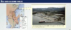
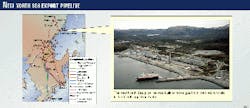
The Statoil/Conoco mid-Norway methanol plant (Fig. 1) has been operating for about 21/2 years. It is an energy-efficient, gas-to-liquids (GTL) plant; its thermal efficiency is close to 70% (84% is the theoretical maximum for methanol production).
The discovery of the Heidrun oil field on the Halten Bank, 175 km off the mid-Norwegian coast, directly resulted in the construction of this methanol plant.
Tjeldbergodden is a strategic investment for the future, because there are a number of new oil and gas fields available offshore. If future methanol demand increases, Tjeldbergodden can increase its production capacity and achieve low unit costs.
This article describes the existing methanol operation and the two planned projects and their expected benefits.
Methanol potential
Statoil and Conoco discovered the Heidrun oil field in 1985. It achieved commercial production in 1995. The field contained large quantities of associated gas, which could not be flared as a result of strict environmental regulations in Norway on emissions of greenhouse gases.
Natural gas had to be converted into a transportable liquid or reinjected in the oil field. Previously, Statoil and other oil and gas companies in the area had transported and sold all natural gas developed in the Norwegian and British sector of the North Sea to Western Europe through offshore pipelines.
Fig. 1 shows the export pipelines in the North Sea (Norpipe, Zeepipe, and Europipes I and II).
The Heidrun field was distant from existing pipelines, however. It is in the Haltenbanken sector, south of the Arctic Circle, about 200 km from the Norwegian coast and about 600 km northeast of the closest point of the existing North Sea gas pipeline grid.
After evaluating several alternatives, Statoil and Conoco decided in 1990 to lay a 250-km, 16-in. pipeline to shore at Tjeldbergodden and build a methanol plant there. The pipeline has been designed to transport up to 2.2 billion standard cu m/year of natural gas. The methanol plant consumes 0.6 billion cu m/year of gas.
Although there is only limited local consumption of methanol in the region, the cost for Statoil to ship methanol to Rotterdam is low compared to those of other competing plants. Competing plants operate in Russia, Libya, the Middle East, Chile, Venezuela, and Trinidad.
The sailing time from Tjeldbergodden to Rotterdam is 50 hr, which gives the site flexibility in serving the customer.
Western Europe is a net importer of methanol. The Tjeldbergodden site has easy access to remote gas fields as well as to markets. As the plant is in Western Europe, dedicated small volumes can be shipped directly to end-users.
The future methanol market will most likely be dominated by three factors:
- MTBE demand.
- Future for methanol-based, fuel-cell automobiles.
- Methanol as a gas-turbine fuel.
In the long-term, accelerated development of fuel-cell vehicles will completely change the future for methanol. Will fuel-cell automobiles run on methanol within 5 years? Could it be a potential niche market in urban areas?
As methanol seems to be the selected fuel among the auto manufacturers, Statoil views these challenges and opportunities positively. Today, Statoil is working with the auto industry to ensure that methanol can be handled safely at the retail level and used to the benefit of both industry and the environment.
The cost of producing methanol will also play an important role.
A typical world-scale methanol plant of 2,500 tonnes/day requires a methanol price around $130/tonne at a gas price of $1/MMbtu to make profit. This corresponds to a methanol fuel price of about $5.8/MMbtu, which is high compared to gasoline or diesel.
There is, however, higher potential energy efficiency in a methanol proton-exchange membrane fuel cell (PEMFC; >35%) than in a conventional combustion engine (< 20%).
Development of new methanol technology focuses on scaling up single-train methanol capacities to greater than 7,500 tonnes/day (equivalent to 22,000 b/d syncrude). If commercialized, these plants may reduce the production cost of methanol to far less than $100/tonne. The cost is even lower if low-quality methanol can be sold.
Methanol performs well in gas turbines. Certain suppliers guarantee the suitability of methanol in their power-generation equipment. Methanol could be a competitive fuel alternative for power production in markets with environmental concerns and where alternatives such as piped gas or LNG are either not available or are too expensive.
Methanol also can be shipped in conventional tankers with no costly new infrastructure.
Process technology
The methanol plant is based on synthesis gas (syngas) production by two-step reforming and a methanol synthesis loop based on boiling-water reactors.
The product-distillation section includes a three-column system. The reforming and distillation section is licensed from Haldor Topsø AS, Lyngby, Denmark, while the methanol synthesis is licensed from Lurgi AS, Frankfurt, Germany.
Selection of technology for making methanol depends greatly on the technology for the production of synthesis gas. The syngas process dominates investment and the overall energy consumption.
A joint Statoil and Conoco project team concluded in 1992 that the most attractive synthesis-gas technology was two-step reforming. Table 1 compares energy consumption, based on flow sheet values, for the four major concepts for production of methanol from natural gas, namely:
- Conventional steam reforming.
- Autothermal reforming.
- Partial oxidation.
- Combined reforming.
Combined reforming is a combination of conventional steam reforming and autothermal reforming.
It was the only process that met Statoil's requirement for CO2-emission levels below a ceiling that corresponds to an overall energy consumption of no more than 30 GJ/tonne of product. This level of energy consumption was a key factor in obtaining plant approval from the Norwegian parliament.
For the methanol synthesis, Statoil and Conoco chose the boiling-water reactor concept mostly because DuPont, the owner of Conoco at that time, had favorable operational experience with this reactor concept at an existing methanol plant on the US Gulf Coast. The concept was also chosen for its high energy efficiency and reliability.
Process description
Fig. 2 shows a simplified flowsheet of the methanol plant at Tjeldbergodden.
The waste-heat-recovery section of the primary reformer preheats the natural gas. A sulfur absorber containing zinc oxide removes acid gas (H2S) at 400° C. After desulfurization, a saturator saturates the natural gas with process condensate.
The saturated natural gas is mixed with a small amount of medium-pressure steam to allow exact control of the steam-to-carbon ratio at 1.8. The gas is preheated to about 500° C. before it is admitted to the prereformer.
The prereformer converts the higher hydrocarbons into methane and CO2. After the prereformer, the gas is further preheated and fed to the primary "tubular" reformer.
The partially reformed gas from the tubular reformer next goes to the secondary reformer, where reforming is completed by autothermal reforming (partial combustion using oxygen followed by catalytic steam reforming, both in one reactor unit).
In the secondary reformer, hydrogen is consumed during the partial oxidation (or combustion). In a tubular reformer, surplus hydrogen is generated. Combining these two process steps produces a balanced synthesis gas.
The balanced synthesis gas and the retention of combustion water are key elements for the process efficiency.
After the reformer section, the syngas is cooled to 30° C., and surplus water is condensed out. Heat from the syngas-cooling train helps produce superheated high-pressure steam and heat to the reboilers in the distillation.
The produced raw methanol is condensed, separated from the recycle gas, and sent to a raw-methanol storage tank before it is admitted to the distillation section.
The methanol-distillation process purifies the raw methanol product to US chemical grade AA standard in a three column system.
Further, the side-fired steam reformer, licensed from Haldor Topsø, can operate at a lower heat flux in the critical top section of the reformer tubes. This makes it possible to operate at a lower steam-to-carbon ratio than more common top-fired reformers. This further improves the energy efficiency of the plant.
The process uses heat from condensing "surplus" process steam in the synthesis gas cooling train for boil up in the distillation section. Finally, the saturator, which vaporizes some 90% of the total process steam demand to the reformers, uses the 36 barg steam generated in the methanol reactors.
Operating experience
Construction of the methanol plant and gas pipeline were completed in the first quarter 1997. Commissioning and testing took about 3 months, and full production occurred in June 1997.
As oil production from the Heidrun field commenced in 1995, Statoil reinjected associated gas during the interim period.
The plant has produced more than 2 million tonnes of methanol since June 1997. The overall experience from operation of one of the most energy efficient methanol plants in the world has been positive.
As a result of unexpected deactivation, believed to be caused by organic sulfur, a new charge of prereforming catalyst was installed during the September 1998 turnaround.
Operators visually inspect the reformer tubes at regular intervals. Thus far, they show no sign of hot banding.
In the past, burners for such applications demanded extensive maintenance. On occasion, certain designs have burned through the refractory insulation and pressure vessel, causing significant damage.
Haldor Topsø and Lurgi are the most experienced licensors of this technology. Haldor Topsø developed a new generation of burners, the CTS burner design, which eliminated the problem encountered with earlier concepts. The first burner of this type was installed in a plant in France in 1992, and has now operated flawlessly for 6 years, much longer than any previous burners.
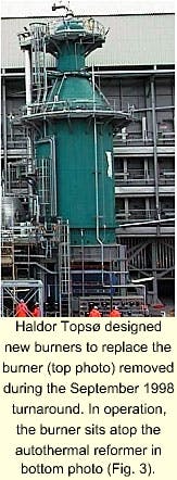
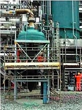
The secondary reformer has performed according to design, but during the scheduled turnaround in 1998, inspection of the secondary reformer burner showed some erosion of the burner tip. Statoil, therefore, replaced it with a CTS burner during the 1998 turnaround.
Fig. 3 shows the secondary reformer and the burner from the September 1998 turnaround.
The soundness of the refractory was proven after the start-up, since no hot spots have been found in connection with this minor damage. Later, a video camera inspection of the transfer line showed that no changes have been found in the condition of the refractory lining.
During the initial run, a few hot spots developed in the field welds in the reformer section. The refractory and these hot spots were inspected and repaired during the scheduled 1998 turnaround.
Ceramic ferrules on the tube inlet of the Tjeldbergodden waste-heat boiler protect the metals from the synthesis gas atmosphere in the hot zone.
Over a period of 3 months, the methanol product intermittently developed a slight fishy-smell caused by TMA (tri-methylamine), an unwanted byproduct. This is a common and known problem in new plants.
To eliminate this problem Statoil adjusted process parameters and tested for TMA. The company analyzed key process streams with off-line gas chromatography to monitor the presence of TMA and its precursors, such as NOx and nitrogen in the syngas and distillation sections.
The TMA analysis has proven reliable down to concentrations less than 10 ppb. It is a valuable tool in optimizing distillation parameters and eliminating the product odor.
The vibration was a result of a pored-designed sealing system. This was fixed during the 1998 turnaround.
Also, the oxygen flow-control valve was initially too small. The control valve was replaced with a higher-capacity valve during the turnaround.
Capacity-expansion projects
Statoil has initiated two expansions to increase its methanol production. These are:
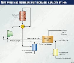
The purge gas from the synthesis loop gas removes inerts, thus keeping the loop in balance. By sending the purge gas through a two-stage, semipermeable membrane separator, the membrane system separates hydrogen from components such as CH4, CO, CO2, and N2. The final H2 stream, with a purity of about 90%, will be fed back to the syngas compressor.
Membrane separators are available from several suppliers and have been in service in the general hydrogen and syngas industry for more than 15 years. The recovery of hydrogen and rejection of residual gas is a common application.
The project includes other minor plant modifications. The project investment is less than $30 million, and the pay-back time is less than 3 years, even at low methanol prices. Statoil plans on implementing this project this year.
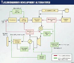
Different reforming technologies under consideration are (Fig. 5):
Concepts under evaluation to increase the methanol synthesis capacity are (Fig. 5):
The initial technical and economical evaluations show that the payback time for this project may be lower than for the project to increase capacity by 10%.
For this project, Statoil has completed a concept identification phase, which includes identification of critical technical elements, with four licensors: Haldor Topsø, Lurgi, Synetix, and Krupp Uhde. Next, it will perform a feasibility study on the two most promising concepts.
A final decision on the scope of the project will be made by the end of 2000.
The Authors
Roger Hansen is R&D manager, gas conversion and petrochemistry, at Statoil. Previously, he was research advisor for synthesis gas and methanol technology.
Hansen participated in the commissioning and start-up of the methanol plant at Tjeldbergodden. He has 12 years of experience in GTL technology, including 2 years in Catalytica, Calif., and 4 years at SINTEF, Trondheim, Norway. He holds an MS in chemical engineering from the Norwegian Institute of Technology, Trondheim.
Ola Olsvik is R&D manager, methanol, of Statoil. He is head of the R&D team which provides technical support to the Tjeldbergodden plant. Olsvik holds a PhD in chemical engineering from Norwegian Institute of Technology, Trondheim.
