Hydrotesting not required under new API-653 procedure
An analytical method has been developed that allows aboveground storage tanks (ASTs) to be returned to service after major repairs without a hydrostatic test.
The method relies on an analysis of the repair or modification welds that calculates critical surface-defect size in the weldment.
API guidelines
In the last 10 years, the standard for AST inspection and repairs on tanks storing petroleum products has been API-653, Tank Inspection, Repair, Alteration, and Reconstruction. Proper application of this standard ensures that tanks are adequately inspected and that necessary repairs are made in a manner that achieves quality and integrity.
For tank repairs, API-653 has guidelines for new materials, welding, design, and testing. Significant repairs are designated "Major Repairs" and subject to additional testing, including hydrostatic testing of the complete tank, before returning to service.
Hydrostatic testing is first addressed in API-653, Section 3, "Brittle Fracture Considerations" for evaluation of existing tank conditions. Old repairs or construction details that do not meet current standards are acceptable in regards to brittle fracture if various conditions are satisfied.
One condition that will allow continued operation with non-API repairs is if the tank has operated in the most severe service or if a tank has been hydrotested. This evaluation applies only to brittle fracture concerns, not to structural deficiencies.
The hydrotest waiver of non-API repairs in Section 3 does not apply to new repairs. New repairs that do not meet API requirements cannot be forgiven by hydrostatic testing the tank (API Inquiry 653-I-09/98).
API-653, Section 10, "Examination and Testing," contains the testing requirements for all repairs. This section, commonly known as the Hydrostatic Test Section, has been recently revised and published in Addendum 3 (December 1998).
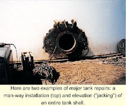
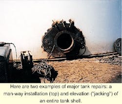
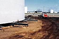
It defines "Major Repairs" as "operations that require cutting, addition, removal and/or replacement of the annular plate ring, the shell-to-bottom weld, or a sizable portion of the shell." Such operations include the installation of large shell penetrations, large shell-plate replacement, extensive repairs to shell butt welds, extensive repairs to the shell-to-bottom weld, installing a new bottom, and "jacking" (elevating) the shell.
A contractor must conduct a full hydrostatic test after major repairs unless the tank owner waives the procedure.
Hydrostatic testing after major repairs is useful for testing for leaks, checking for settlement of new foundations, and confirming the structural integrity of tank repairs. In some cases, however, water is unavailable for hydrotest or is excessively difficult to dispose of.
API-653 Section 10 also gives practices and procedures for exempting major repairs from hydrotest. The guidelines for hydrotest exemption are given in Paragraph 10.3.2. Examples of hydrotest exemption include tanks with thinner shells in warmer climates, shells meeting minimum toughness requirements, small corner weld repairs, and minor jacking.
One method given for exempting major repairs from hydrotest is Fitness-For-Service Evaluation, Paragraph 10.3.2.6. An API standard for fitness-for-service evaluation has been approved. This is API-579, API Recommended Practice for Fitness-for-Service.
Fitness for service
Section 1, Paragraph 1.1, of API 579, API Recommended Practice for Fitness-For-Service, contains the following statement:
The ASME and API design codes and standards for pressurized equipment provide rules for the design, fabrication, inspection and testing of new pressurized vessels, piping systems and storage tanks. These codes do not address the fact that equipment degrades while in-service and deficiencies due to degradation or from original fabrication may be found during subsequent inspections. Fitness-For-Service (FFS) assessments are quantitative engineering evaluations that are performed to demonstrate the structural integrity of an in-service component containing a flaw or damage.
The scope section of API-579 also states that the document is intended to "supplement and augment" the requirements in API-510, API-570 and API-653.
The introduction to the 1991 version of Published Document PD-6493, "Guidance on methods for assessing the acceptability of flaws in fusion welded structures" from the British Standards Institute, provides further clarification of the fitness-for-service evaluation of welds. (This document will be replaced by BS-7910.)
The introduction to this document contains the following:
In circumstances where it is necessary to examine critically the integrity of fusion-welded joints in new or existing constructions by the use of non-destructive testing methods, it is also necessary to establish acceptance levels for the flaws revealed. The derivation of acceptance levels for flaws in welds is based on the concept of 'fitness for purpose.' By this principle, a weld in a particular fabrication is considered to be adequate for its purpose provided the conditions to cause failure are not reached, after allowing for some measure of abuse in service. . . .
Quality control levels (for inspection limits) are, of necessity, both arbitrary and usually conservative and are of considerable value in monitoring of weld quality during production. Flaws at or less severe than such quality levels as given, for example, in current application standards, are acceptable without further consideration.
Fracture-mechanics analysis
These statements provide the core of the procedures proposed here for proving that repaired or modified ASTs are fit-for-service without the imposition of a hydro test.
The procedure involves a fracture mechanics-based analysis of the welds used in the repair or modification with the goal of calculating a critical surface-defect size for the weldment.
If the calculated critical size is larger than the rejection limit for the inspection procedures used to evaluate the weld integrity, then the tank's repairs are exempt from the requirements of hydrotest for integrity.
Fracture-mechanics methods form the basis of both API-579 and PD-6493. In fracture mechanics, the fundamental equation is the following:
KIc = a * s * square root of(p * a)where:
KIc = The material fracture toughness.
a = A constant related to the geometry of the defect and the stress field for the application.s = The stress at the defect location calculated as if the crack were not present.a = A measurement of the crack size, usually the depth of the crack in the case of a surface defect.
In the basic fracture-mechanics equation, if the material toughness is known and the highest expected stress level has been calculated, the defect size (a) can be found for any assumed geometry. This is the fundamental procedure used in evaluating repairs or modifications to ASTs.
If the defect size calculated is larger than the acceptance limits for the inspection procedures used, the tank is considered to be fit-for-service without hydro testing.
Assessment
The specific steps required to perform a fracture-mechanics assessment (FMA) for a tank are as follows:
- Obtain inspection reports showing existing wall thickness for shell courses and tank bottom.
- Obtain copies of weld procedures to be used in tank repair or modification.
- Obtain tank dimensions, fill height, and specific gravity of contents.
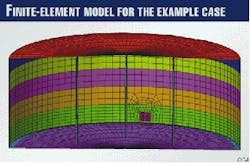
- Construct and analyze a shell finite-element model of the tank to obtain stress information at repair or modification region under study.
- Obtain specimens of welds for shell-to-bottom weld or butt welds using the new material to be installed welded to a piece of the existing shell or bottom for toughness testing.
- Obtain fracture toughness test data (either KIc or crack-tip opening displacement-CTOD) in the heat-affected zone (HAZ) of old material side of the weldment at the lowest expected operating temperature (API-650, Fig. 2-2).
- Use stress at weld and material fracture toughness to calculate critical surface-defect size for a full tank.
- Compare calculated critical size with acceptance limits for inspection procedures used to inspect the new welds.
Items 1 through 3 in this list are needed to complete Item 4, the finite-element analysis (FEA). Items 5 and 6 aim at obtaining fracture-toughness data on the weldments.
Item 7 ties the stress analysis and the fracture toughness together in the FMA. Item 8 is the "Go" or "No go" decision point in the fitness-for-service evaluation.
There are, of course, other ways to accomplish the evaluation. For example, rather than conduct a finite-element analysis, standard pressure vessel calculations could be used to obtain stress information.
This approach, however, may produce higher stresses than really exist, especially if conservative "design" equations are used. Also, standard equations may miss high stresses at the shell wall- to-bottom weld located under stiff, thick insert plates in the wall.
For the measurement of fracture toughness, Charpy data could be used. By use of toughness correlation equations, the material toughness could be estimated from Charpy data at the lowest operating temperature.
While this method can be useful, it is more accurate to obtain and test actual test specimens with the materials and weld procedures used in the repair or modification.
It should be noted that this procedure aims at evaluation of out-of-service tanks. It is entirely possible, however, to perform the FMA for tanks in service. This type evaluation must be considered a "first cut" at the problem of tank repair and must be evaluated further after the tank has been taken out of service.
Nevertheless, it is possible to take a material sample from the tank sidewall or the bottom plate while the tank is in service. These samples are called "boat samples" and can be cut from the wall with a cut-off wheel. The pit remaining should be no deeper than 25-37.5% of the wall thickness.
This sample can be used to measure the material toughness of the old shell or bottom plate material. The evaluation of the weld HAZ cannot be done in this way, but the base-material toughness can provide useful analysis to predict the probability of avoiding a hydro test after repair.
Example
In this example, the tank has a diameter of 100 ft (30.48 m), a height of 40 ft (12.19 m), a fill height is 39 ft (11.88 m), and fluid specific gravity of 0.77. The tank has an internal floating roof with a structure supported cone roof (Fig. 1).
The object of this analysis is the weld between the shell lower course and the door sheet shown in Fig. 1. The shell lower course has a measured minimum thickness of 0.535 in. (13.59 mm), and the new door sheet is 0.625 in. (15.87 mm) thick.
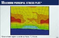
Fig. 2 shows the maximum principal stress on the outside surface of the tank, 6.02 ksi (112 Mpa). It may be noted that the FEA mesh in Fig. 2 is rather coarse around the door sheet.
The adequacy of the mesh size was confirmed in this instance by constructing a much finer mesh sub-model of the door sheet region. This analysis produced the same stress levels and stress pattern as shown in Fig. 2. Hence, the mesh shown in Fig. 1 was proven to be adequate.
This is typically the case when using shell elements with mid-size nodes. The normal mesh size requirements applied to solid FEA models do not always apply to shell element models.
In this example, samples were obtained of the new door sheet material and the old shell material using the door sheet cutout. These plates were butt welded with the same materials and procedures used in the field modification.
The welded plate was sent to a testing laboratory where critical CTOD test specimens were machined and tested according to ASTM E-1290, the CTOD testing standard.
The notch and fatigue crack in these specimens was located in the HAZ of the weld on the old plate side of the weld. This region typically produces the lowest values of material toughness.
Three tests were conducted at 0° F. (-18° C.); the lowest CTOD value measured was 0.006 in. (0.152 mm).
The next task is to select a fracture-mechanics crack model. Because a commercially available fracture-mechanics analysis code is to be used in this analysis, the simplest thing to do is to select one of the models available in the code.
The code, called FractureGraphic (FG), is sold and maintained by Structural Reliability Technology Inc., Boulder, Colo. The crack geometry assumed for this analysis is a surface crack in a flat plate with the crack perpendicular to the maximum stress. The stress used in the analysis is 20 ksi (140 Mpa).
This value was chosen by increasing the FEA calculated stress of 16 ksi (112 Mpa) by 25% to produce a conservative critical defect size estimate. This stress will be conservatively assumed to be uniform through the wall thickness of the plate.
The FractureGraphic code automatically adds a secondary residual stress to the applied stress for cases in which there is a weld that is not stress relieved.
In this case, the assumed secondary stress is equal to the material yield strength, or 36 ksi. For the case of a butt weld in a flat plate, the FG code assumes that the residual stress is uniform through the plate thickness.
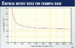
Under the conservative stress and the lowest measured CTOD value from the test data, the critical defect sizes were calculated. Fig. 3, which presents the result, is a plot of combinations of sizes of surface crack length and depth that are critical.
One way to use this plot conservatively is to draw two lines extending the asymptotes of the curve at each end. Where these two lines cross will define a conservative estimate of critical crack dimensions.
In the case of this example, the conservative estimate of the critical crack size for inspection purposes thus becomes 26.89 mm (1.059 in.) in surface length by 4.63 mm (0.182 in.) deep.
If inspection of the weld at the door sheet has been conducted with normal procedures and qualified personnel, the critical size limit can be compared with the acceptance limits for the method used.
If magnetic particle or liquid-penetrant inspection methods were used, the ASME code states that no linear indications are acceptable and that rounded indications shall be no larger than 0.1875 in. (4.76 mm).
Hence, it is clear that the critical defect size conservatively estimated from the fracture analysis is larger than the inspection limits. Therefore, the tank is considered to be fit-for-service without hydro testing.
The Authors
Steve Caruthers is the president of Tank Consultants Inc. He has 28 years' experience in the design, construction, repair, and inspection of aboveground storage tanks. Caruthers is a professional engineer and an API Authorized Inspector. He serves on the API committee for API-650 and API-653, standards for construction, repair, and inspection of tanks.
Ronald E. Frishmuth is an independent consulting engineer who has been working in applied engineering mechanics for more than 30 years. He worked in mechanics of materials and customer service at General Electric Co.'s gas-turbine division, and in the engineering properties group at Alcoa Laboratories and the materials engineering group at Cameron Iron Works. Frishmuth also worked for nearly 6 years as the manager of the structural analysis group at ABB Vetco Gray. He holds a PhD in theoretical and applied mechanics from the University of Illinois.
