High dogleg severity, wear ruptures Chinese casing string
A combination of high dogleg severity, swelling shales, and internal casing wear led to a ruptured casing string in the Tarim oil field of the Xinjiang Province, China.
Acting upon this information, personnel from China National Petroleum Corp. evaluated the events that led to the incident and formulated guidelines to avoid such occurrences in the future.
Background
The accident occurred in January 1997 after testing well X1 for 15 hr. Over the next 12 hr, crewmembers reverse-circulated clean water, with some chemical additives (KZ-01), at a pump pressure of 12-18 MPa.
Subsequently, a total of 162 cu m of mud (mud density = 1.24-1.34g/cu cm) was recovered. However, engineers calculated that 6 cu m of mud did not return to the surface, indicating a condition of lost circulation.
After the crews shut down for 10 min to reconfigure the hydraulic system, flow was completely choked off.
The driller then kicked the pumps out, applied 169 tonnes of overpull to the casing string (hanging weight = 147 tonnes), but had no success in moving the string. Crewmembers then reconnected the kelly and applied 10 MPa of pump pressure, again with no success.
Under a load of 150-180 tonnes, the drillers continued to work the string up and down for 24 hr, but the stuck point would not move.
Unfortunately, conditions worsened as the well then lost total circulation.
Treatment of the accident
At this point, it became necessary to back the pipe off above the stuck point through left rotation applied under 160 tonnes of tension. After the string was backed off, the driller measured a hanging string weight of 122 tonnes, a fish length of 2,235.73 m, and a fish top at 4,317.24 m. The top of the fish consisted of a 88.9-mm tool joint.
After running a 200-mm lead stamp to the top of the fish at 4,315.16 m and applying 1.5 tonnes of pressure, the driller found two symmetrical wear traces on the side of the lead stamp but no mark on the bottom. It was thought that casing deformation caused the symmetrical traces on the sides of the lead stamp.
Next, crew members ran a wiper trip to just above the fish and resumed circulation with 3 to 20 MPa of pump pressure. The fish top was measured at 4,317.24 m. Then the crews ran a caliper survey using a Circumference Acoustic Scanning Tool (CAST) and measured the diameter of the casing from 4,250 to 4,315 m.
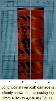
It was found that the 244.5-mm casing string was damaged from 4,254 to 4,270 m and 4,300 to 4,315 m (Figs. 1-5, Table 1). Figs. 1 and 3 show the gauge results at 4,190-4,234 m and 4,289-4,315 m. Among these, Figs. 1a and Fig. 3a display deviation, Gamma API, and relative bearing (RB) while Figs. 1b and 3b show amplitude.
It was shown that abrasion and wear caused by drillstring rotation and corrosion reduced the echo received by the transducer. Thus, an obvious difference between the damaged and normal areas can be clearly seen on the logs.
Figs. 1c and 3c display the variable radius. The red and black indicate that the radius is greater than the nominal internal radius of the casing. The yellow coding indicates that the radius is less than normal internal radius of the casing.
Figs. 1d and 3d show the maximum, minimum, and average ID.
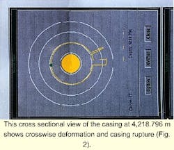
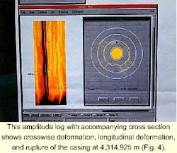
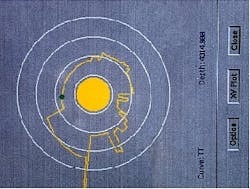
Figs. 2 and 5 show the crosswise deformation and rupture of the casing at the depths shown. Fig. 4 shows the crosswise deformation, longitudinal deformation, and rupture of the casing at 4,314.925 m.
The deformed condition of the casings below 4,315 m was not measured because the CAST tool could not get past 4,315 m. It was clear from pipe sticking and fishing operations that the 244.5-mm casing ID was less than 127 mm because the 88.9-mm drill pipe with 127-mm tool joint was stuck.
The CAST log shows that the casing was deformed and ruptured at the wellbore from 4,253 to 4,315 m. Analysis of the final accident indicated that the casings were also deformed at the wellbore from 4,315 to 4,325.23 m. - Crosswise deformation and rupture of the casing also occur at 4,314.988 m (Fig. 5).
Freeing the string
After evaluation of a condition of casing deformation from the logs, the stuck pipe was freed through a washover operation and 16 joints of drill pipe were fished out.
Unfortunately, the operation became too difficult as time progressed, and the washover pipe ruptured. It was known from the result of the washover that the annulus at the bell position, which formed between the bottom of 244.5-mm casing and the top of 177.8-mm casing, was filled with solid mud material. The annulus between the 177.8-mm casing and 60.3-mm drill pipe was also in the same situation. Thus, the operator abandoned the well.
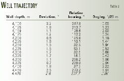
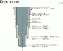
Upon examination of the casing program and well trajectory (Fig. 6, Table 2), it is clear that a dogleg promoted a condition of casing deformation.
Openhole section
In the 215.9-mm openhole section, underneath a 244.5-mm casing string, crews spent a total of 2,007 hr drilling, 638 hr on 28 round trips, and 618 hr on redressing and reaming operations (51 events). The specific gravity of the mud was 1.91-2.05 g/cm (40-50% barite) with a viscosity of 78-98 sec.
The drillstring assembly included the following components:
- 215.9 mm bit.
- 177.96 m of 158.8-mm OD drill collars.
- 9.95 m of 158.8-mm OD drilling jars.
- 26.6 m of 158.8-mm OD drill collars.
- 126.53 m of 127-mm heavy wall drill pipe by.
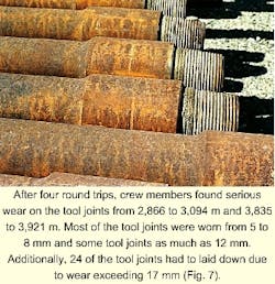
After four round trips, crew members found serious wear on the tool joints from 2,866 to 3,094 m and 3,835 to 3,921 m.
Most of the tool joints were worn from 5 to 8 mm and some tool joints as much as 12 mm. Additionally, 24 tool joints had to be laid down due to wear exceeding 17 mm (Fig. 7). It was assumed that the corresponding internal wall surface of the casing string also underwent serious wear.
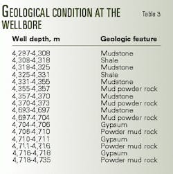
Table 3 shows occurrences of shale, mudstone, and powder mud rock at the well depths where casing deformation occurred. And at the well depths where most serious casing deformation occurred, paste (gypsum rock) and mudstone were found.
Analysis
The CAST log showed that there were longitudinal damages and ruptures (Fig. 1), but the casing cross section remained basically round at 4,206-4,230 m and 4,253-4,270 m.
The degree of casing damage gradually worsened as the circular cross section of the casing changed to an elliptical shape from 4,303 to 4,325.23 m (Figs. 3-5). And the circular cross section of the casing formed an irregular oval with a minimum diameter of 152 mm and a maximum diameter of 458 mm. The rupture occurred in the direction of the maximum diameter. Casing damage and breaches possessed features associated with events of collapse and rupture.
It is clear from the results that from the beginning, the pipe became stuck and the pump choked up as the annulus was filled with solid mud materials, which then settled in the annulus. After this condition began, the casing underwent deformation.
Additionally, a reduction in hydrostatic head affected the situation as crewmembers displaced the 1.51 g/cu cm drilling fluid, at a depth of 4,315 m, with water. Calculations are as follows:
- For the hydrostatic pressure of the weighted drilling fluid, P1, at 4,315 m.
P1 = 4,315 m x 1.51 g/cu cm x 0.0098 = 63.9 MPa - For the hydrostatic pressure of water, P2, at 4,315 m.
P2 = 4,315 m x 1.00 g/cu cm x 0.0098 = 42.3 MPa - To calculate the reduction in internal pressure, P, at 4,315m.
P = P1 - P2 = 63.9 - 42.3 = 21.6 MPa
Reasons
Therefore, it was impossible for this particular casing string to burst at 38 MPa as the casing and cement quality at the depths of deformation were good. In addition, if the casing burst due to internal pressure, the rupture would form a "bamboo leaf" shape instead of a "linear" shape.
Additionally, the cross section of the casing would have swollen. This was not in agreement with the observed features of the damaged casing.
However, a condition of casing collapse could be created through a reduction in internal casing pressure through the displacement of mud with water, compounded by formation swelling acting on the exterior portion of the casing.
Basically, the internal pressure rapidly drops as the pump shuts down, so that the total collapse force acting on the casing includes the pressure change of the pump and the reduced pressure caused by a loss in hydrostatic pressure.
This condition happened several times as the pumps were kicked in and out. Consequently, the reduction in internal pressures, when alternating between 18 and 38 MPa, can be calculated under the following two conditions:
- While kicking the pump out at 18 MPa, the total reduced internal pressure should include the reduced pump pressure and the difference in hydrostatic pressure between water and mud. The former is 18 MPa, the latter is 21.6 MPa with:
Pt1 = 18 + 21.6 = 39.6 MPa - Likewise, turning off the pump at 38 MPa would reduce the internal pressure as follows:
Pt2 = 38 + 21.6 = 59.6 MPa
According to theoretical calculations, the collapse strength of the casing is 70.7 MPa (10,260 psi). This is well above the first condition stated above at 39.6 MPa and is 56% of the theoretical collapse strength of the casing. In comparison, the remaining wall thickness would have to have been about 6.71 mm if the casing were to have collapsed at 39.6 MPa.
The second condition also falls well within this threshold with a calculated internal pressure of 59.6 MPa, or 84.2% of the theoretic collapse strength of the casing. In this case, the remaining wall thickness would have to be about 10.10 mm.
Casing test
Subsequent analysis included a full-size collapse test that resulted in 65.2 MPa before the casing was breached. The features of this test were similar to the actual damage observed from the well.
The reduced internal pressure under the first condition (39.6 MPa) is 60.8% of the measured collapse strength of the casing. Thus, the calculated remaining wall thickness would be about 7.29 mm if the casing collapsed at 39.6 MPa.
Additionally, the second condition of reduced internal pressure (59.6 MPa) would result in a rating of 91.6% of the measured collapse strength of the casing. Thus, the calculated remaining wall thickness calculated for this case would be about 10.98 mm if the casing collapsed at 59.6 MPa.
Causes of rupture
Engineers concluded that the casing was damaged during well testing after completion of the upper hole section. The 244.5-mm casing remained undamaged before and during the cement operation as the pressure build up showed good results affected by good cement quality. Thus, the casings must have been damaged in a later drilling operation.
Caliper results showed doglegs of up to 2.2°/25 m at the well depths where the casings were seriously damaged. This condition was supported by continuous well activities as the well endured 2,007 hr of drilling with a 215.9-mm bit under the 244.5 casing. Thus, the 244.5-mm casing string must have been worn by the drillstring at the well depths where large doglegs occurred.
The casing collapse resistance must have been severely reduced once the casing was badly worn. Workers have shown that a reduction in dogleg severity forms a key preventive measure against casing wear (OGJ, Aug.1, 1994, p. 30).
The heavily worn casing, occurring at a point of high dogleg severity, probably could not support the pressure test and could have easily caused the casing to rupture. Additionally, it has been shown a high number of round trips will increase the total extent of casing wear.1
Swelling
At the well depths where the casing was seriously damaged, the formations consisted of 11 m of mudstone (4,297-4,308 m), 19 m of shale (4,308-4,318 m), and 7 m of mudstone (4,318-4,325 m).
Mudstone and shale both produce conditions of swelling, with the latter rock type contributing most to this condition. Swelling will therefore apply high collapse forces on to the outside surface of the casing string. As a result, the 244.5-mm casing string became stuck while running it in the hole.
Furthermore, the hydrostatic pressure fell while displacing mud with water, worsened by a sudden drop in internal pressure as the driller kicked the pump out. In effect, the casing would collapse and rupture as the external force became greater than the collapse strength of the casing.
Recommendations
For future operations, the following conditions should be met to avoid another event such as this one:
- Reduce dogleg severity.
- Adopt measures to prevent casing abrasion in drilling and trips.
- Record the amount of wear on the drill stem as a method for evaluating casing wear conditions.
- Extend the casing string to be used in well testing to the ground.
Reference
- Schoenmakers, J.M., Koninklijke/Shell E & P Laboratories, "Casing Wear During Drilling: Simulation, Prediction, and Control," SPE Drilling Engineering, December 1987.
Acknowledgments
The authors thank Terry Changyi for his ideas during composition and review of this article both in English and Chinese. The authors also thank William R. Warke for his suggestions and revisions in English to the manuscript.
The authors
Lu Shuanlu is a research engineer at the Tubular Goods Research Center for China National Petroleum Corp. Since 1983, he has worked on aspects of failure analysis, inspection, and supervision of tubular casing and drillstrings.
Li Zhihou is a director general of the drilling department in the Tarim oil field for China National Petroleum Corp. He has 30 years' experience in drilling dynamics, tubular engineering, and well design.
Han Yong is a vice-president at the Tubular Goods Research Center for China National Petroleum Corp. He has 17 years' experience in well design, tubular engineering, and failure analysis.
Li Pingquan is a vice-president at the Tubular Goods Research Center for China National Petroleum Corp. He has 30 years' experience in metal material and failure analysis.


