Horizontal wells provide bilinear pressure signatures
A limiting equation may explain the unexpected pressure signatures that appear to indicate bilinear flow in horizontal-well pressure analysis.
These pressure signatures often occur unexpectedly when testing horizontal wells in homogeneous reservoirs, but this phenomenon has received little attention in petroleum literature.
The pressure signature of the vertical bilinear flow period is controlled by the distance between the well and the closest boundary, zw, the length of the well, Lw, and the directional permeabilities, kz and kx.
The limiting equation for bilinear flow in the horizontal plane is more accurate than the corresponding equation for bilinear flow in the vertical plane. Its accuracy was about 10% for the cases investigated, and this may be explained by the uncertain height of the equivalent plane source.
Bilinear flow
A bilinear-flow period appears as a straight line of one-quarter slope when the pressure derivative is plotted on a log-log coordinate system. The occurrence of such a line in a reasonably homogeneous reservoir could be caused by an unknown geometric factor, or it could represent true bilinear flow. But bilinear flow is a plausible interpretation.
This bilinear flow may be thought of as two linear-flow periods occurring simultaneously in perpendicular regions.
This concept is a one-dimensional idealization of flow in three dimensions. As such, it may be valid only during a limited time period.
Bilinear flow may occur either in the horizontal or the vertical plane. Both cases may be approximated by simple limiting equations that were verified by comparing the results from the bilinear-flow models against a three-dimensional, line-source solution.
The interaction between a horizontal well and the exterior boundaries may lead to several specific flow periods.1 Most researchers expect radial or linear-flow periods to appear.
Du and Stewart investigated pressure responses of horizontal wells.2 According to the them: "...field examples quoted in [their paper] do not show this feature (linear flow) as often as one might anticipate and unexpectedly quarter slopes have been observed in many cases." After this statement, they show that bilinear flow may occur for double porosity and layered reservoirs.
Jelmert and Vik observed that horizontal wells in homogeneous reservoirs may also have responses that appear to be bilinear.3
Flow periods
Traditional well-test analysis is based on the existence of specific flow periods, such as radial, linear, bilinear, and spherical.
The underlying conceptual models are based on simplifying assumptions regarding flow geometry. This approach leads to simplified limiting equations, which may be used to aid well-test interpretation.
The existence or nonexistence of possible specific flow periods is important for identifying the most probable reservoir model.
A conventional assumption regarding flow towards a horizontal well is that the regions beyond the tips do not contribute to initial production. The side regions, therefore, may be neglected.
If the reservoir is infinite acting in the vertical direction, the result is radial flow in the vertical plane. But later, the pressure response may be influenced by the upper and lower boundaries of a no-flow boundary that leads to linear flow. Inactive side regions cause this.
Eventually, the area beyond the tips cannot be neglected, and there is a possibility of pseudoradial flow in the horizontal plane.1
The assumption of inactive side regions may not always be valid and this requires a more complicated model.
An extension of the linear-flow model allows the side regions to have some influence. Because of the long length of a horizontal well, it is assumed that only the region in between the tips contributes significantly to initial production. The effect of the side regions is limited to feeding fluid into the main flow path that is perpendicular to the well.
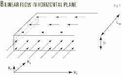
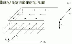
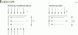
Linear flow results from a flow in the primary region that is dominated by an upper and a lower boundary of no-flow. But if the flow in the side regions is near linear, the result is bilinear flow (Fig. 1).3
Fig. 1 also shows the directional permeabilities. In this case, the well axis is perpendicular to the direction of highest permeability.
In a region where most of the flow is linear, a line-source well may be replaced, with minimum error, by a source in the form of a plane. Then the mathematical problem becomes simplified because a one-dimensional model is sufficient and limiting equations are readily available.
A plane source may be thought of as a uniform flux fracture. The height of the plane-source during horizontal bilinear flow is defined by the distance between the upper and the lower boundaries, for example the reservoir height, h.
The horizontal extension of the plane source, however, is uncertain. With the conventional assumption of inactive side regions, the horizontal extension is equal to the length of the well, Lw. This length is also assumed to be the horizontal extension of the plane source in the bilinear flow model (Fig. 1).
The difference between linear flow towards a plane and line source is that the latter has an additional pressure drop due to convergence of flow close to the well. This may be accounted for by a steady-state pseudoskin factor.
Pressure derivatives usually identify the specific flow periods. The constant pressure drop associated with the skin, therefore, disappears and the accuracy of a simplified model may be checked against a three-dimensional model by comparing the derivative responses.
Bilinear flow is also possible in the vertical plane. The early occurrence of this in the bilinear-flow period may be explained by an initial elliptical or pseudoradial flow in the vertical plane that, because of the directional permeability, results in the pressure disturbance traveling further in the horizontal than in the vertical direction.
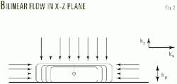
The elliptical geometry will change once the pressure disturbance is influenced by the nearest horizontal boundary. The no-flow boundary condition forces the isobars to intersect the boundary perpendicularly (Fig. 2). In Fig. 2, the isobars are close to rectangular.
Because the flow lines are perpendicular to the isobars, the almost-rectangular shape may induce bilinear flow.
The height of the vertical plane source, hp, is uncertain because the flow is influenced by only one physical boundary. One can expect, however, that the height of the imaginary plane source is about twice the distance between the well and the closest boundary, for example hp aproximately equal 2zw (Fig. 2).
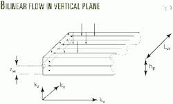
The horizontal extension of the equivalent plane source is also uncertain. Again it is assumed that this distance is equal to the well length, which is consistent with the traditional assumption for linear flow (Fig. 3).
Pressure signature
Fig. 4 shows the similarity between the flow towards a finite conductivity fracture and a horizontal well during vertical bilinear flow. The corresponding streamlines are almost identical. Hence, the two cases may be described by similar equations. The main differences are the existence of a skin factor and a different nomenclature.
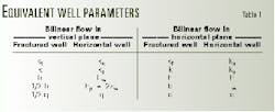
When one equation is available, the other may be obtained by substitution of parameters, as shown in Table 1.
The first three substitutions are obvious, but the last two are different from simplistic substitutions. The reason is that, the fracture model of Cinco-Ley and Samaniego accommodates flow from both sides of the hydraulically fracture.4 In the horizontal flow model, however, the inflow into the main flow region is limited to one side by a no-flow boundary.
By symmetry, the centerline of the hydraulic fracture is a no-flow boundary. The required system of one open and one closed boundary is obtained when one limits the calculations to one half of the fracture. The one-half-fracture correction may be done by reducing both the production rate and fracture aperture by a factor of 1/2, for example 1/2b and 1/2q (Fig. 4).
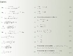
Cinco-Ley and Samaniego derived Equation 1 to predict the pressure response for bilinear flow in a finite conductivity fracture.4 Parameters k and kf denote formation and fracture permeability, respectively, while b denotes fracture aperture.
Replacing the fracture flow parameters with the horizontal well equivalents in Equation 1 yields Equation 2, where DPSv denotes pressure loss due to the pseudoskin. The zw denotes the distance between the well and the closest boundary. The kz and kx, respectively, denote the directional permeabilities in the vertical and horizontal direction perpendicular to the wellbore axis (Fig. 3). Equation 2 plots as a straight line on a pressure-vs.-fourth root of time plot. The intercept with t1/4 = 0 axis is DPSv. Equation 3 gives the slope of the straight line. The equation of the slope provides a relationship between the three unknowns, kz, kx, and zw.Two more equations are required to solve all of these equations. In some cases, such information exists or may be estimated. Whether or not such information exists, Equation 3 may aid well-test interpretation.
Substitution of the dimensionless parameters from Equations A1, A2, and A5 into Equation 2 yields Equation 4, the dimensionless equation for vertical bilinear flow. The index v denotes bilinear flow in the vertical plane.
The effect of a skin factor disappears during a derivative operation. Hence, the occurrence of a bilinear-flow period may be verified by a pressure derivative, for instance the logarithmic one.
Equation 5 provides the logarithmic derivative. This equation will be a straight line with a quarter slope in a log-log coordinate system.
Jelmert and Vik proposed an equation for bilinear flow in the horizontal plane.3 Table 1 lists the relevant substitutions.
Replacement of the fracture flow parameters with the horizontal well equivalents in Equation 1 yields Equation 6. Index h denotes bilinear flow in the horizontal plane. The ky and kx, respectively, denote the directional permeabilities parallel and perpendicular to the wellbore axis (Fig. 1).
Substitution of the dimensionless parameters, Equations A.1, A.2, and A.5, into Equation 6 yields Equation 7. The logarithmic derivative of Equation 7 is given by Equation 8.
This conceptual model is based on the assumption of flow in the horizontal plane only; hence the equations are independent of the vertical permeability, kz, and the position of the well, zw. These parameters will influence the skin factor, Sh, because the vertical-flow component is limited to the skin zone.
Case studies
In contrast to what conventional theory predicts, the early linear-flow period occurs rarely for horizontal flow.2 All of Horne's horizontal well examples illustrate this point.5 His Tests 5, 11, and 20 are all clearly closer to bilinear flow than to linear.
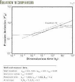
Kuchuk shows an example that has two segments of near-bilinear behavior.6 This example was selected to illustrate bilinear flow. Fig. 5 lists the relevant reservoir data. To compute the infinite-acting reservoir response with the analytical model, one assigns the large distances between the outer boundaries, LxD and LyD.
This case study illustrates the accuracy of the proposed limiting equations for vertical, Equation 5, and horizontal bilinear flow, Equation 8. The results then are compared to those obtained by the line-source model of Thompson.7
Substitution of the data from Fig. 6 into Equations 5 and 8 yields Equation 10 for bilinear flow in the vertical plane and Equation 11 for bilinear flow in the horizontal plane (Fig. 5).
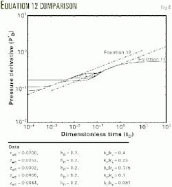
Fig. 6 illustrates the result that the limiting equation for vertical bilinear flow could be improved by Equation 12 rather than Equation 10.
The late straight line in Fig. 5 is the logarithmic derivative under the horizontal bilinear-flow assumption, given by Equation 11. The accuracy of this limiting equation is better than the corresponding one for the vertical plane, Equation 10.
The interpretation is that there is no uncertainty of the height of the equivalent plane source. This distance is defined by the upper and lower no-flow boundaries. This seems to justify the assumption that the horizontal extension of the equivalent plane source is equal to the length of the well.
From Equation 5, one may be conclude that all reservoirs that may be characterized by the same numerical value of CF, given by Equation 9, have similar pressure signatures. The dimensionless group defined by CF will be referred to as the correlating factor.
To test the bilinear-flow models further, the parameters were varied such that CF was a constant equal to 1.778. This was obtained by changing the permeability ratio, kz/kx and adjusting the distance between the well and the closest boundary, zw, accordingly. Reservoir height, hD, is kept constant. Fig. 5 lists the relevant data.
Fig. 6 shows five curves and two straight lines. The curves indicate the logarithmic derivative of the analytical solution for Thompson. The flow periods, in chronological order, on the curve are vertical radial, transition period (near bilinear), hemiradial in the vertical plane, bilinear, and finally pseudoradial flow.
Equation 12 is for the early straight line, observed while Equation 10 gives the theoretical line. As discussed previously, both the vertical and horizontal extension of the equivalent plane source are uncertain for bilinear flow in the vertical plane. A difference of only 10% between the observed and theoretical response, therefore, seems to support the interpretation of bilinear flow in the vertical plane.
One can infer that the deviation between the theoretical and observed limiting equation is due to an inaccurate assumption regarding the height of the equivalent plane source only. This error could be corrected for by assuming that this height is hp = 2azw rather than hp = 2zw, where a is a coefficient to be determined by numerical experiments.
By combining Equations 5, 10, and 12, it is easy to calculate that a = 0.81 for this series of runs. Then zw should be replaced with 0.81 zw in the dimensional equations, Equations 2 and 3. The constant a may be lumped together with the other constants in Equation 5. The correlation factor, therefore, remains unchanged. Similar calculations could be made for other values of CF.
The experiment confirms that CF is a correlating factor for bilinear flow in the vertical plane. All curves approach the same limiting line, given by Equation 12. Furthermore, the bilinear flow in the horizontal plane is not significantly influenced by the previously mentioned changes in the vertical permeability and the distance between the well and the closest boundary.
The latter observation is consistent with the interpretation of bilinear flow in the horizontal plane. The vertical permeability has negligible effect because there is no flow in the vertical direction except within the skin zone.
Because the theoretical responses assumed sources in the form of planes, it is reasonable to expect that restricted entry vertical fractures of high conductivity, uniform flux or infinite conductivity, may also induce flow that appears bilinear. This possibility, however, was not investigated.
References
- Odeh, A.S., and Babu, D.K., "Transient Flow Behavior of Horizontal Wells, Pressure Drawdown, and Buildup Analysis," Paper No. SPE 18802, SPE California Regional Meeting, Bakersfield, Calif., April 1989.
- Du, K.F., and Stewart, G., "Transient Pressure Response of Horizontal Wells in Layered and Naturally Fractured Reservoirs With Dual Porosity Behavior," Paper No. SPE 24682, 67th SPE Annual Conference and Exhibition, Washington DC, Oct 4-7, 1992.
- Jelmert, T.A., and Vik, S.A., "Bilinear flow may occur for horizontal well," OGJ, Dec. 11, 1995, pp. 57-59.
- Cinco-Ley, H., and Samaniego, V.F., "Transient Pressure Analysis for Fractured Wells," JPT, September 1981, pp. 1749-46
- Horne, R.N., Modern Well Test Analysis. A Computer Aided Approach, 2nd Edition, Petroway Inc., 1995.
- Kuchuk, F.J., Goode, P.A., Wilkinson, D.J., and Thambynayagam, R.M.K., "Pressure-Transient Behavior of Horizontal wells with and without Gas Cap or Aquifer," SPE Formation Evaluation, March 1991, pp. 86-94.
- Thompson, L. C., Manrique, J., and Jelmert, T., "Efficient Algorithms for Computing the Bounded Reservoir Horizontal Well Pressure, Response," Paper No. SPE 21827, SPE Joint Rocky Mountain Meeting and Low Permeability Symposium, Denver. Apr. 15-17, 1991.
The author
Tom A. Jelmert is currently on a sabbatical at the Colorado School of Mines, Golden. He is professor of petroleum engineering at the Norwegian University of Science & Technology, Trondheim, and previously was a research engineer at SINTEF, Trondheim, and an adjunct professor of mathematics and physics at the Academy of the Royal Norwegian Air Force. Jelmert holds a BS in electrical engineering from Purdue University and an MS and PhD in petroleum engineering from the Norwegian Institute of Technology.
