Deepwater pipeline repair system uses proven tools
After years of planning and design, Shell International Exploration & Production Co., Houston, has developed a deepwater pipeline repair system (DPRS) that uses proven technology.
The repair system incorporates many of the tools and connection systems that the company has used on several construction projects.
- The sled concept for pipeline termination has been used by Shell and others successfully to land a pipeline on the seabed with an upward looking hub.
- The connectors purchased for the DPRS have similarly been proven on other projects.
- Metrology for spoolpiece fabrication has been successfully accomplished on projects using both acoustics and taut-line systems to measure hub orientation plus vertical and horizontal separation between connector hubs.
Behind the decision to proceed with the DPRS was a desire to reduce as much as possible the time required to effect a repair.
By calling for the purchase of all the connectors and tooling necessary for a repair, this DPRS concept has eliminated the long lead-time required for the equipment, which may be as lengthy as 50-60 weeks.
The DPRS is flexible and adaptable to address a range of repair scenarios. With an on-bottom and surface-lift solution, the system is configurable for numerous repair scenarios.
The system consists of several components, including pipeline-end manifolds, diamond wire saw, end-preparation tool, concrete and coating-removal tool, hydrate-detection tool, leak-detection tool, release-containment tent, diverless clamps, grip-and-seal connectors, recovery tools, and pipe-lift frames.
Gulf discoveries push thinking
The economic and environmental effects of a deepwater pipeline rupture have long been major drivers to invent and develop a deepwater pipeline repair system. Ever since pipelines have been installed in deepwater (greater than 1,000 ft), Shell and others have endeavored to develop methods for repairing damage.
Such US Gulf of Mexico discoveries in the 1980s as Bullwinkle, Auger, and Mars prompted Shell to think about how these deepwater assets might be returned to service in the event of an anchor snag, dropped object, collapsed pipe, or other event that rendered the line out of service.
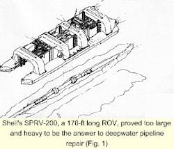
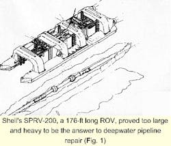
Deepwater development at this time was still in its infancy, without much standardization of components or practices. Novel concepts, such as the Shell's SPRV-200, were efforts to answer the complex issues surrounding deepwater challenges.
Often, the answer posed as much of a challenge as the questions: The SPRV-200 (Fig. 1) was an unmanned remotely operated vehicle (ROV) that was 176 ft in length and weighed more than 1,500 kips.
In January 1990, a joint industry research and development program published its findings in a two-volume set entitled "Deepwater Pipeline Repair Methods."
Recommended at the time was a surface layover method, in which both ends of the damaged pipeline are cut out, recovered to the surface, the two ends joined together with a curved connecting spoolpiece, then the connected pipeline is lowered to the seafloor in a direction perpendicular to the pipeline route.
This required the lay barge with the tensioning capacity for two strings of pipeline, as well as the right-of-way to lay the pipe over. This method would not be workable in deepwater because, even today, only one string exceeds the load limit of several lay barges, depending on such variables as pipe size and water depth.
Over the years, tools and partial solutions have addressed pipeline repair, such as recovery hooks, drop-on clamps, and pipe lift frames. But all of these approaches failed to address a systems approach for performing a deepwater pipeline repair.
Recognizing the gaps in the existing repair tools, Shell Deepwater Producing Inc., Equilon Enterprises, and Shell Gas Transmission in September 1998 agreed to develop a deepwater pipeline repair system (DPRS).
The resulting system and the parameters that governed its design comprise the remainder of this article.
Low probability; high consequences
The DPRS is designed for all oil and gas export lines in the US Gulf of Mexico in water depths beyond diver intervention. The main intent of the system is to minimize the downtime of the export pipeline if a failure should occur.
It was recognized early that the probability of a deepwater pipeline failure is low. But the event is also of "high-consequence": Once it does happen, getting the pipeline back into service quickly is critical.
These characteristics of a deepwater pipeline repair dictated the DPRS be flexible and consist of as much proven technology as possible.
To these ends, several facets of the repair system have been addressed, including the following:
- Development of repair procedures and manual.
- Development, manufacture, and testing of connectors and tooling necessary to perform a repair.
- Analysis, design, and fabrication of jumpers.
- Development of hydrate-remediation procedures.
- Development of commissioning and start-up procedures.
A value-engineering workshop sponsored by Shell in October of 1997 selected the surface-lift repair method, described presently, as the most reliable and acceptable method for repairing a damaged deepwater pipeline.
After funding was secured and the project team began working on the project, it was realized that an on-bottom solution was also necessary.
This requirement was dictated by the fact that there may be occasions that prevent recovery of the pipeline to the surface, such as in the case of pipeline damage near another pipeline crossing.
Other circumstances may make a surface lift unfeasible, such as unavailability of a heavy-lift vessel and proximity of damage to a riser.
These realizations led the project team to develop two repair methods, surface lift and on-bottom. With the myriad of possibilities a damaged pipeline may present, both solutions have been designed for flexibility.
Both solutions consider the following line sizes: 12, 14, 16, 18, and 20 in., with operating pressures up to 6,000 psig at 120° F.
Both methods use conventional rigid jumper spool technology and collet connectors to connect one end of the repaired pipeline to the other end.
The difference between the two solutions lies in how the upward-looking male hub is placed on the end of the pipeline.
Repair solutions
Surface-lift repair relies on a heavy-lift vessel to retrieve the pipe to the surface, which allows welding of the hubs to the end of the pipes (as opposed to a mechanical connector) and access to the pipe bore for remediation of hydrates.
Once the pipeline is lifted, a male hub is welded to the pipe end, clamped to a pipeline end manifold (PLEM), and deployed back to the seabed.
These steps are repeated for the other side of the cut pipeline to leave two upward-looking hubs on the seafloor.
Either acoustics or taut-wire technology is then used to determine the relative angles and slant range between the hubs. These measurements are used to fabricate a jumper, which is then deployed to the hubs on the seafloor.
Hydraulically actuated collet connectors incorporating metal seals are utilized on the ends of the jumper to make the connection between the two pipeline sleds. The repaired pipeline is then ready for commissioning.
In the on-bottom repair, pipe-lifting frames elevate the end of the pipe above the seafloor to allow cut out the damaged pipe and preparation of the end of the pipe with a concrete and fusion-bonded epoxy (FBE) removal tool and end prep tool.
A gantry sled-PLEM assembly is then landed near the end of the pipe, which allows the ROV to position a grip-and-seal connector, already welded to an elbow with an upward-looking male hub, onto the end of the pipe.
After actuating the grip-and-seal connector, testing the seal, and removing the gantry frame, the system is configured similar to the surface-lift repair, with two upward-looking male hubs that are latched onto by a jumper with collet connectors.
The surface-lift repair allows a welded connection to be made to the pipe in lieu of an elastomeric seal if the pipe were to be repaired on the seabed. The surface-lift repair, however, places more emphasis on vessel capabilities. This requirement varies depending on pipeline size and at what depth it is damaged.
A repair manual describes all the engineering, hardware, and offshore procedures associated with a repair effort.
Connectors
The connection type selected for jumper connectors for the surface-lift repair is a metal seal collet connector manufactured by Oil States Industries, Dallas.
These connectors have been used in several subsea connections similar to the system described here and provide good misalignment tolerances, high strength, and good operability.
A desire to mitigate the high capital-equipment costs related to purchasing connectors for each size of pipeline led to the concept of sleeving the connectors. This concept uses a 20-in. integral collet connector, which is sleeved down to any of the other four sizes to cover the range of pipelines being protected by the DPRS.
The on-bottom repair utilizes Hydrotech's grip-and-seal connector, which provides an elastomeric seal element that is squeezed to form a seal around the outside diameter of the pipeline.
Grips plastically deform the pipe to provide a mechanical connection between the connector and pipeline. This type of connector, with the help of the gantry frame (described presently), allows installation of the upward-looking hub and elbow onto the end of the pipeline without the requirement of welding.
It is anticipated that inline diverless spool connections will become the accepted method for connecting diverless jumpers using new ROV-operated bolted-flange technology.
As this technology acquires a track record similar to the collet connectors and grip-and-seal connectors, the system can be modified to utilize bolted flange, in-line spool components by welding a swivel ring flange directly to the grip-and-seal connector.
Gantry frame, PLEM
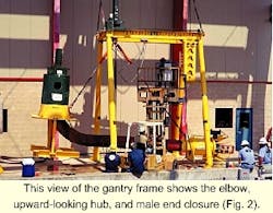
The on-bottom repair requires installation of the grip-and-seal connector, elbow, and hub onto the end of the pipeline on the seafloor. For this operation, Hydrotech has designed two gantry-frame PLEMs, which are lowered to the seafloor on a down line.
An ROV operates the gantry frame to position the grip-and-seal connector over the end of the elevated pipe end. After testing the seal, the ROV will lock down the assembly to the mudmat with clamps, which will transfer most loads from the connector-pipeline into the mudmat.
The gantry frame structure can then be removed from the assembly to leave it configured as the surface repair system on the bottom, with two upward-looking hubs ready for jumper measurement.
By addition of the pivoting yoke to the base, the mudmat of the gantry frame PLEMs becomes the mudmat used for the surface-lift repair method, reducing the cost and size of the DPRS system.
Preliminary designs for a skirt bolted to the mudmat provide some contingency for landing the sleds on an inclined seabed.
Fig. 2 shows the gantry frame, with the elbow, upward-looking hub, and male end closure.
Lift frames; hooks
Lifting frames from the URSA project, which used 18 and 20-in. OD pipe, have been modified to handle all sizes of export lines protected by the DPRS.
These frames are used to lift the pipe off the seafloor for either attaching a recovery hook in the case of a surface-lift repair or providing an elevated pipe tip for cutting and preparing the end of the pipe, as well as installation of the grip-and-seal connector via the gantry frame.
Recovery hooks consist of both overshot-type tools and drop-on recovery tools. The type of tool used for lifting depends on the damaged pipeline and the configuration of the as-laid pipeline (whether j-lay collars are available to react to the load).
ROV tooling
There are a number of ROV tools needed to perform tasks for the surface lift and on-bottom repair scenarios. Some of the tasks required of the ROV include cutting the pipe, removing concrete or FBE coating or both, capturing any hydrocarbon product that may be escaping from the pipeline, and measuring the distance between hubs for jumper fabrication.
Tools built to accomplish these tasks include the following:
- Diamond-wire cutting module (DWCM).
- Concrete and FBE-removal tool (CFRT).
- End-preparation tool (EPT).
- Isolated hydraulic power supply (IHPU) and module-docking skid.
- Discharge containment tent (DCT).
- Hydrate detection tool (HDT).
- Premeasurement tool (PMT).
- Hump trap lift frame.
Two contractors have been selected for supplying the majority of the ROV tooling. Sonsub Inc., Houston, has developed the diamond-wire cutting module, concrete and FBE-removal tool, end-preparation tool, and an isolated hydraulic power supply and module-docking skid.
Oceaneering International, Houston, was awarded the discharge-containment tent, hydrate-detection tool, and hump-trap lift frame. Oceaneering has also provided Shell on a previous project with a premeasurement tool for performing jumper metrology.
Each of these tools is described below.
Cutting module
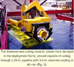
The diamond-wire cutting module, originally developed for Sonsub's diverless sealine repair system (DSRS), will cut both concrete weight-coated and FBE-coated steel pipelines. The module consists of two sub-assemblies, the cutting module and the clamping module.
The cutting element is a special diamond-coated wire, formed into a closed loop. The cutting module consists of an arc-shaped tubular frame that houses a high-speed traction pulley with its motor.
This pulley plus the two free pulleys that are located at the two ends of the frame support the diamond wire. One of the two pulleys is mounted on a mobile arm operated by an hydraulic cylinder that is used to keep a constant tension on the cutting wire.
The clamping module is an hydraulic clamp that keeps the machine clamped to the pipe to be cut. It is built from an upper rigid structure, supporting four moving arms operated by hydraulic cylinders.
The upper structure and the mobile arms are supplied with reduction kits profiled according to the diameter of the pipe to be clamped.
The system is designed for deployment to the sea bottom on a deployment frame, which also holds the end prep tool and concrete and FBE-removal tool.
Once deployed to the seafloor, the DWCM is moved to the pipeline and operated by a work class ROV.
In third quarter 1999, trials demonstrated that the tool could cut through a 20-in. pipeline with 3.5-in. thick concrete coating in approximately 45 min.
Fig. 3 shows the diamond-wire cutting module clamped to the deployment frame.
Concrete, FBE-removal tool
The concrete and FBE-removal tool is designed to remove efficiently both the concrete weight-coating and FBE coating from the pipe surface to allow a connector to be installed over and sealed to the outside of the cut pipe.
The tool operates on pipe sizes between 12 and 36-in. pipes with up to 4.5-in. thick, reinforced concrete weight-coat (that is, 45 in. maximum pipe OD).
This tool has a clamping arrangement that is similar to the diamond-wire cutting module for clamping to the pipeline. Mounted to the frame is a pair of extend-and-retract cylinders capable of moving a tooling plate along the pipeline up to 3 ft.
There are two concrete cutting heads, mounted to the front rotating tool plate, that work together to remove all concrete and FBE from the pipe surface efficiently.
The cutting heads are designed to eliminate potential damage to the pipe surface and leave it with a surface finish similar to that achieved by sand blasting.
End-preparation tool
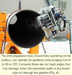
The end-preparation tool cleans burrs and ragged edges from the end of subsea pipelines after they have been cut with Sonsub's diamond-wire cutting module.
The tool ensures that there are no rough edges that may cause damage to either the connector seals or any future pigs run through the pipeline. It is operated via two hot stabs from the ROV isolated hydraulic power supply and is positioned onto the end of the pipe by the ROV manipulator.
It operates on pipe sizes ranging from 8 to 36-in. OD. Fig. 4 shows the end-preparation tool operating on the surface.
Power supply; docking skid
The IHPU allows the ROV to provide isolated hydraulic power to the tools required to execute a repair and to actuate and perform high-pressure external seal tests on the pipeline connectors.
Also included is the docking system to allow for an in-water mechanical connection to the cutting module and coating-removal tool for seafloor deployment by the ROV.
The modular power unit allows the major components to be distributed within the frame of an ROV.
Hydraulic power is provided to the tooling modules through standard dual port hot stabs and a special high-flow hot stab. The IHPU provides the following circuits:
- A 10,000-psi circuit for performing external seal tests of the pipeline connectors and actuating the grip-and-seal connectors.
- A high flow, 20 gpm, 2,000-psi circuit, required for operating the cutting module and the coating-removal tool cutting and removal heads.
- A 3-gpm, 3,000-psi circuit for operating the various module functions such as clamping etc.
- The system reservoir provided with the system provides a 5.5-gal capacity.
Containment tent
The discharge containment tent (DCT) is designed for pipeline repair and associated release mitigation. It can be used as both a first response to pipeline damage to control the release until the pipe can be repaired and as a capture device to place over the cutting module when a cut is being made.
The DCT is a "tent-like" structure, with a frame fabricated from 2-in. OD aluminum pipe. The fabric covering of the DCT is a highly durable, urethane-coated nylon fabric.
The DCT is designed so that during deployment and recovery, the fabric along the top and sides of the tent can be retracted against the rear wall.
The DCT contains a centrifugal pump powered by the ROV via a hot stab.
The pump moves product from the top of the DCT to two containment bladders, which can be recovered independently to the surface for disposal of the fluid.
Fig. 5 shows the discharge containment tent being lowered over the diamond-wire cutting module.
Hydrate-detection tool
Oceaneering designed the hydrate detection tool, in conjunction with Synetix Services and the Shell E&P Technology Co., to detect hydrate plugs in pipelines.
Synetix's Tracerco gamma-ray transmission equipment has been used in the gulf since 1990 to locate hydrate plugs.
The system, which consists of a low-strength radioactive source and detector, works by placing the source and detector on opposite sides of a pipe.
Measuring the absorption of the source's gamma waves through the material determines the average density of the sample. Once a baseline has been established for a specific pipeline transporting a particular fluid, variations in density can be measured.
From these data, hydrate locations and magnitude can be determined. This information is transmitted to the surface via a twisted-pair electrical conductor in the ROV umbilical.
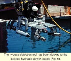
The detection tool is designed to roll along the top of the pipe, carrying the equipment on a stable platform, and allow for continuous real-time scanning of the pipe.
The ROV docks into a bucket on the detection tool that interfaces with the IHPU in a manner similar to the cutting module and the coating-removal tool, which allows the ROV to move the detection tool along the pipe.
The source and detector are mounted in housings that can be adjusted to fit pipelines ranging from 12 to 20 in. OD. The housings can be positioned so that they are in line with the centerline of the pipe.
J-lay collars and anodes present an obstacle for the tool sled rolling along the pipe. Rather than lift the sled off the pipe and fly over the obstacle (which could be as often as every 160 ft), the sled has been designed to roll over these obstacles.
Fig. 6 shows the hydrate-detection tool docked to the IHPU.
Lift frame; measurement tool
The hump-trap lift frames are a set of pipe-lift frames developed to minimize a pollution incident. Raising the pipe off the seafloor above the elevation of the damaged section creates a "trap," which limits the volume of the release to the volume between the local maximum and the damaged section.
These frames are designed to work with the various sizes of pipes from 12 to 20-in. and can lift up to 29 kips.
The premeasurement tool has been designed, fabricated, and tested to measure distances, relative bearings, and elevations between subsea structures. The tool will be used to determine the spool-piece length and configuration required between the upward-looking collet connector hubs.
The tool is designed to be a relative measurement device rather than an absolute one. When the subsea measurements (both linear and angular) are repeated with identical receptacles on the surface, the relative positions of the two subsea connector hubs can be simulated to a high degree of accuracy.
Spoolpiece
Installation and operational loads, as well as fabrication and measurement tolerances, govern the configuration of the spoolpiece that has been analyzed by the Shell E&P Technology Co.
Consideration for thermal expansion of the pipeline, as well as measurement and fabrication tolerances are some of the variables that must be addressed in the design of the jumper to prevent overstressing either the pipe or connector.
The process and all required analysis tools have been developed so that an engineer assigned to a repair project can perform the required engineering work to design the spoolpiece for either repair scenario (on-bottom or surface-lift repair).
A work package associated with the spoolpiece fabrication and testing will be contracted out at the time of the repair. Jumper fabrication will take place at a dockside location using prefabricated jumper sections and fabrication and measurement jigs.
Once the jumper metrology is completed, the measurements will be used to set up the fabrication stands to complete construction of the jumper. After inspection of the welds and hydrotesting of the jumper, it will be shipped out to location, run to the bottom on a spreader bar, and latched to the male hubs on the PLEMs.
At this point commissioning can begin. Fabrication of a jumper for SIT has also been a part of this work.
Hydrate location
Hydrates, which are crystalline compounds formed by combination of water and components in natural gas, can completely impede the flow in a pipeline. High pressures and low temperatures are conducive to hydrate formation, which may occur in both oil and gas pipelines.
Virtually all of the existing hydrate-plug detection methods are indirect, such as monitoring pressure drops, monitoring pigging returns, or a drop in water production rates.
Shell E&P Technology Co., Oceaneering, and Synetix worked together on the hydrate-location problem. The ROV tooling section earlier in this article contains a description of the hydrate-detection tool.
Shell E&P Technology has also developed hydrate-disassociation curves for the various pipelines operated by Shell. The disassociation curves, based on product composition, assist in determining how best to remediate any hydrate after it has formed.
The authors
Tom Preli is the staff engineer at Shell International Exploration & Production, Houston, responsible for Shell's Gulf of Mexico deepwater pipeline repair project. He joined Shell in 1989 and has been involved in the company's pipeline operations in the Gulf of Mexico.
Preli holds a BSCE from Texas A&M University and an MSCE from Purdue University. He is a registered professional engineer in Texas and Louisiana.
Jeffrey M. McCalla is a senior engineer for Big Water Inc., New Orleans, having previously held several positions with Oceaneering and Sonat Subsea Services. He has served for 4 years as a third-party contractor to Shell, providing ROV consulting on the Mensa and Macaroni felds. McCalla holds a BSME from Louisiana State University, Baton Rouge, and an MSOE from the University of New Hampshire, Durham.
