Control-system improvements expand refinery processes
Despite their often secondary consideration, process-control improvements can generate substantial benefits with little or no investment.
Four examples from Koch Petroleum Group refineries show how poor process control significant affected plant profitability: two gas plant examples, one hydrotreater fractionator example, and one deisobutanizer example.
These cases do not represent an exhaustive list of potential opportunities. Nearly every refinery or chemical plant has similar circumstances waiting to be discovered. Sometimes poor control goes unnoticed because changing an operating procedure that has been practiced as long as any operator can remember is difficult.
Evaluating a unit's process control with the goal of stabilizing unit operation and a detailed knowledge of the process enables the process engineer or process-control engineer to develop new control schemes that dramatically improve unit performance and profitability.
Dynamic processes
In today's competitive refining environment, refiners often neglect or overlook possible changes in instrumentation and process controls when looking for ways to increase operational efficiencies. This is a grave mistake because these systems can provide low-cost improvements in an existing process, often with no or little capital.
One of the most common mistakes when looking for process bottlenecks or potential improvements is to look at a process plant as a steady-state environment, often with a commercial steady-state simulator.
All chemical and refining processes are dynamic environments, subject to changes in feed composition and flows, utility-quality variations, and upsets in upstream units. Even if something is controlled directly, like feed flow to a unit, if not accounted for, the variation in flow can cause premature constraints downstream.
Thus, it is necessary to analyze a refining process with an understanding of its dynamic nature.
In general, the effort required to set up a dynamic simulation so that it is sufficiently accurate to draw valid conclusions is not justified. The required information can be framed using a steady-state simulator and final tuning conducted after the control modification is made.
In many cases, simulation is not even required to achieve the desired outcome.
Any debottlenecking study should include a review of the process controls, preferably with input from key equipment suppliers and unit operators. This procedure identifies potential improvements and ensures that new equipment is properly designed for the way the process operates.
The following examples illustrate opportunities in which revamping process-control systems solved particular unit problems.
Gas-plant flooding, Case 1
In 1997, Koch Petroleum Group's Pine Bend, Minn., refinery experienced flooding of the stripper and debutanizer in the gas plant associated with its fluid catalytic cracking unit (FCCU).
In the office, Koch engineers ran a simulation of the gas plant to observe more closely what was happening in the unit. They provided the simulation results and the resulting tower loads to Koch Glitsch for evaluation.
The tray ratings, while well in excess of 80% of flood for both towers, were certainly within normal operating ranges. Towers theoretically flood at 100% of flood. The unit should not have been flooding.
Fig. 1 shows a flow diagram of the gas plant.
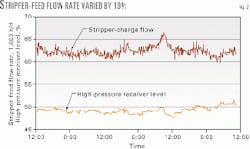
Further investigation of the problem revealed that the simulation used average unit flows over a several-hour period. Analysis of real-time data showed that the feed-flow rate to the stripper from the high pressure receiver varied by as much as 10% over the course of this period, as shown in Fig. 2.
These flow variations cascaded to the debutanizer, where they also caused flooding. Adjusting the simulation to reflect the higher rates verified that the trays were flooded at the resulting conditions.
In fact, the simulation showed that the impact of the poor feed-flow control was even larger than it first appeared. Because the stripper-reboiler controls could not effectively respond to the variation in the stripper feed, the operators placed them on manual mode to maintain control of the C2 concentration in the debutanizer-overhead product.
This manual control resulted in a constant heat input for the highest flow experienced. At low flows, the column was over reboiled, resulting in an LPG recycle between the stripper and the high-pressure receiver, which magnified the effect of the flow variation.
The root cause of the flow variation was the level controller on the high-pressure receiver (Fig. 2). For 3 days, the level of the receiver varied by less than 4%. This limited movement translated to a variation of less than 1 in. in a 12-ft ID vessel.
Some time prior, the refinery must have adjusted the tuning parameters to maintain very tight control of the vessel level at the expense of unstable flow. In response to this realization, Koch readjusted the tuning to allow variation between reasonable levels. A "gain scheduling" package, which allows the tuning constants to vary depending on deviation from set point, further improved unit operation.
Increasing the allowable range of the high-pressure receiver level increased gas-plant capacity by about 7%.
It is worth noting that the level displacer on this vessel is only 14 in. long. A relatively low-cost improvement would have been to increase the displacer size and modify the level controller to a volume controller. Turnaround timing has prevented such a displacer modification to date.
A volume controller allows greater level swings within the same limits, stabilizing the flows even further. Implementation of a volume controller eliminates the nonlinear impact of controlling level in a large horizontal vessel with a large displacer.
Gas-plant flooding, Case 2
A gas plant similar to the one in Case 1 experienced flooding of its stripper during one winter. The unit averaged more than one upset per week.
Stripper flooding resulted in FCC rate cuts of several thousand barrels at different times to bring the stripper under control. These cuts almost always sent high levels of C2s to downstream olefin processing units, sometimes resulting in flaring from those units.
Investigation showed that the cooling-water supply temperature to the wet-gas compressor aftercoolers and absorber intercoolers was too low. Although it usually ran about 80° F. in warmer weather, the refinery kept it at about 65° F. in the winter to maximize cooling for other key exchangers. The result was a decrease of about 20° F. in the high-pressure receiver temperature, condensing more C2s into the stripper feed. The increased vapor traffic overwhelmed the trays.
The inset in Fig. 1 shows a revised control system that fixed the problem. A new line rerouted a portion of the absorber bottoms liquid directly to the high-pressure receiver, bypassing the compressor aftercoolers. Operators can now manipulate the flow of this bypass to control the high-pressure receiver temperature.
The temperature indicator must be located carefully to avoid stagnant areas in the vessel (pump suction or discharge piping being a preferred location). Tuning is also important to avoid the level and temperature controllers from "fighting" each other.
The solution to the problem, installing the new line, was not simple because it required waiting for the next unit shutdown for required piping modifications. In this case, the refiner's alternatives were either to do nothing and live with the upsets or to regulate the cooling-water flow to the exchangers.
The refiner chose to regulate the cooling water flow until the new control system could be installed. At the end of run, inspectors found that the exchangers were heavily fouled with mineral deposits as a result of low water velocities and high film temperatures. Some of the tubes were completely plugged.
Overhead-pressure control
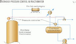
The flow and instrument lines in Fig. 3 show a common pressure-control scheme employed on crude towers, FCC main fractionators, and just about every other type of column with an overhead-vapor product.
It is relatively simple to configure and tune, and it does a good job of controlling reflux-accumulator pressure. Its only weakness is its ability to control tower pressure in climates where significant changes in ambient temperature occur during the course of the day.
Typical fin-fan installations consist of one or more exchanger bays with large fans to move air over the tubes. Manual switches, typically mounted at grade near the fans, control the driver motors for them. Because it requires manual intervention, this on-off control results in substantial variations in heat removal in the fin-fan exchangers.
The temperature pinch that typically exists with the cooling water in the trim condensers dampens this variation before the process fluid gets to the overhead accumulator. A temperature pinch occurs when the shell and tube side temperatures are so close that there is no driving force for heat transfer.
The pressure drop through the fin-fans can vary substantially, however, as a result of the change in pressure drop across the exchanger system. The variation in how far vapor progresses before it is condensed determines this pressure change.
Fig. 4 illustrates the impact on overhead pressure for a typical column. When the overhead pressure varies widely, the tower overhead pressure varies within a very limited range.
The red line in Fig. 3 shows how the refinery, upon the recommendation of Koch-Glitsch, modified the overhead system of a distillate-hydrotreater fractionator to control the column-overhead pressure.
The modification was simple because the pressure measurement from the stripper was already available in the control system, which is typical. If it had not been available, it would not have been difficult to install a pressure transmitter on a bleed on the overhead line while the process was on line.
Although the pressure drop through the overhead-vapor line influences this pressure measurement, it is preferable to no measurement at all.
A final consideration in the control-system configuration revealed that a low limit should be maintained on the overhead accumulator. This low limit prevents pulling a vacuum at that location.
Implementing this control scheme on the column resulted in an estimated 4% increase in light product yield due to improved pressure control.
DIB pressure fluctuations
In a separate example, Koch's deisobutanizer (DIB) column experienced pressure fluctuations which made it difficult to maintain alkylate Rvp targets. These fluctuations also resulted in periodic flooding of the DIB and reduced isobutane recovery.
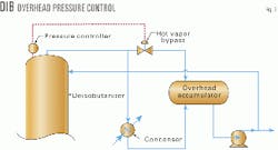
The column overhead system, shown in Fig. 5, consisted of a condenser mounted at grade with an elevated overhead accumulator. The refiner used a hot vapor bypass from the condenser inlet to the overhead accumulator to control pressure.
This configuration is a common pressure-control scheme. It allows for easy maintenance access for the condensers and control valve. As well, it offers the advantage of cost savings on the valve and minimal support structure. This valve is smaller and cheaper than a valve placed in the overhead vapor line for direct pressure control of the tower.
It can also be subject to several problems, however.
In this case, Koch had hired a major control-systems company to do a plant wide audit. The company documented the DIB pressure control as a major opportunity for upgrading.
It identified the nonlinearity of the existing control scheme as the major problem and recommended that pressure be controlled directly rather than by regulating cooling-water flow.
Regulating cooling water is infeasible as a result of the potential fouling that can occur when cooling-water velocities are too low. Moreover, such an approach misses the root cause of the problem.
The overhead isobutane product from this column is recycled to the alkylation unit, and operators manually regulate the flow to maintain a stable isobutane/olefin ratio in the reactors.
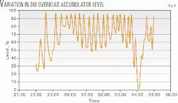
Fig. 6 shows the resulting variation in accumulator level. This variation in liquid level is transmitted through the piping to the grade-mounted condenser.
Since this pressure-control scheme works by varying the number of tubes exposed for condensing vapor, this level variation translates directly to a pressure variation. In this case, as a result of the size of the accumulator vessel, column pressure varied by as much as 2 psi.
Koch found that stabilizing the level minimized pressure variations. Improving the control of the feeds to the column, especially a refinery mixed butane stream fed to the unit for isobutane recovery, stabilized the isobutane recycle flow.
As the final benefit, alkylate Rvp stabilized, allowing for reduced giveaway in the gasoline product.
The authors
Dana Laird is a refining technical consultant at Koch-Glitsch Inc., St. Paul, Minn. His responsibilities include revamp-scope development, start-up assistance, and troubleshooting. Before 1997, he worked for Koch Petroleum Group in Wichita, Kan., and Pine Bend, Minn. Laird has 13 years' experience in process design and refinery technical services for FCC and crude-unit revamps. He holds a BS and an MS in chemical engineering from the University of Kansas, Lawrence. He is a registered professional engineer in Kansas.
John Cornelisen is a senior control engineer at Koch Petroleum Group LP. He is also control, digital, and analytical systems lead for the company. He has 9 years' experience as a field engineer in instrumentation and process-control engineering for the refining industry. Cornelisen holds a BS in chemical engineering from the University of South Florida, Tampa.


