Fire-damage assessment cuts reconstruction cost, plant downtime

Use of a structured approach to damage assessment after a major process plant fire minimized reconstruction costs and the time necessary to resume production.
A recent refinery fire illustrates application of API's Recommended Practice for Fitness-For-Service (API RP 579) and additional practical principles in such an approach.
This article describes the methodology used for the damage assessment by assignment of heat-exposure zones. It focuses primarily on the evaluation of pressure vessels, heat exchangers, and piping systems. A complete assessment includes a documentation package.
The accompanying box highlights practical application tips useful to others faced with a similar situation.
Without a structured fire-damage assessment approach, the natural tendency is to overestimate the amount of equipment that must be replaced and to spend more money for reconstruction than necessary-both of which lead to prolonged unit downtime.
In spite of everyone's best efforts, major fires sometimes occur in process plants. These incidents can result in personnel and physical losses. Once personnel have been cared for and the fire is extinguished, attention then focuses on reconstructing the unit and getting it back into production as quickly as possible.
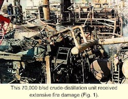
A major fire in a 70,000-b/sd, crude-distillation unit of a refinery also affected three reactors in two nearby hydrodesulfurization units. Fig. 1 illustrates one area of the crude unit that received extensive damage.
The refinery formed a fire-damage assessment team to evaluate the equipment condition and determine necessary steps to return the unit to safe operation as quickly as possible. The team consisted of engineering specialists in materials, mechanical, civil, and process safety, plus onsite inspection and mechanical personnel.
Assessment methodology
The fire-damage assessment took about seven 10-hour days. It addressed the integrity of the equipment materials, mechanical design, and associated civil and structural designs. Specifically, it looked at pressure vessels, heat exchangers, and piping systems affected by the fire.
The evaluation procedures in API RP 579 provided guidance in determining heat-exposure zones and the fitness-for-service of pressure equipment subject to fire.
A three-level system forms the basis of fitness-for-service evaluations:
- Level I is a very conservative screening. It considers only metallurgy and temperature exposure.
- Level II considers metallurgy, temperature exposure, and inspection findings.
- Level III is a detailed evaluation using stress analysis and materials testing.
Except for one case, the refinery evaluated all the damage observed in the crude-distillation unit fire using either a Level I or Level II approach. Based on this experience, the authors expect that most equipment exposed to severe fires will not require a Level III evaluation.
Although this particular fire was very severe (lasting more than 10 hr), the team had no difficulty developing recommendations without performing more-detailed evaluations.
Because the recommendations were so obvious for this severe fire, it is logical to conclude that, for most fire incidents, the appropriate conclusions will also typically be obvious after performing relatively simple inspection procedures or metallurgical tests.
Engineers performed a Level III analysis in a case concerning the bottom nozzle and head of the crude oil distillation tower. The nozzle seemed slightly distorted on observation, but a finite element stress analysis confirmed that this distortion was acceptable without repair.
Heat-exposure zones
The first step in a fire-damage assessment is to identify the "heat-exposure zones" within the fire area. This is the most critical activity of the assessment since all inspection plans and fitness-for-service evaluations follow from this.
The heat-exposure zones also help determine the boundaries for demolition-particularly for piping, instrumentation, and electrical systems. The maximum temperature that occurred in an area during the fire, which is not necessarily the metal temperature of the equipment, establishes the heat-exposure zone for an equipment item or region within a unit.
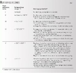
Table 1 summarizes the six heat-exposure zones defined by API RP 579.
It is important to remember that the heat-exposure zone temperatures refer to the external temperature in the various fire regions, not necessarily the equipment or piping metal temperature. The heat exposure dictates the action that must be taken to verify the equipment integrity, for example, inspection, or further fitness-for-service evaluations.
The equipment and pipe metal temperatures actually reached determine the extent of metallurgical damage and the need for replacement. Thus, the refinery can often retain equipment that was protected from the fire temperature by external insulation or cooled by internal liquid for use.
In these cases, the refinery does nothing more than a confirming inspection and hydrotest.
Examples of equipment reuse
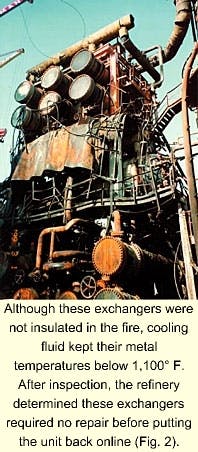
The shell-and-tube heat exchangers shown in Figs. 2 and 3 illustrate the safe reuse of equipment after fire damage. These two exchanger banks were in Zone VI and V, respectively.
Although the exchangers in Fig. 2 were not insulated, the fire did not significantly raise their shell metal temperatures because they contained cool liquid. Therefore, very little external oxidation occurred, indicating a metal temperature of less than 1,100° F.
The exchangers in Fig. 3 were externally insulated, which protected the shells from any damage or appreciable oxidation, that is, scaling. There was some scale in areas that were not protected by insulation or where the insulation was blown away during firefighting.
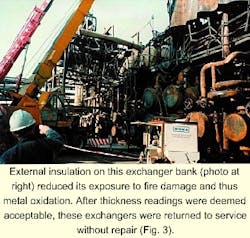
Thickness measurements showed that the actual metal loss was minimal, however, and hardness measurements confirmed that there was no reduction in material strength.
Another example further illustrates the point regarding equipment reuse potential after fire exposure:
The fire-affected area had 22 carbon steel heat exchangers and five carbon steel pressure vessels that experienced temperatures greater than 1,350° F. (Zone VI) during the fire.
Of these, only three pressure vessels and six air-cooled heat exchangers were damaged beyond repair. Three tube bundles required replacement. A local overload caused by collapsing pipe and structural steel damaged three shell-and-tube heat exchangers, which required replacement shells.
Twenty-six carbon steel heat exchangers and six carbon steel pressure vessels were within Zone V (800° F. to 1,350° F.) of the heat-exposure categories. All were acceptably returned to service without repair.
Assigning heat-exposure zones
The key to establishing the heat-exposure zones in the unit is identifying various telltale clues that could be used to estimate exposure temperatures. The clues to look for deal with the expected visual condition of materials after fire exposure.
These include:
- Melting points of materials like aluminum, glass, and steel.
- Appearance of paint and other coatings at various temperatures (for example, paint blistering).
- Appearance and degree of carbon steel oxide scale after exposure to elevated temperatures.
- Appearance of nearby structural steel components (for example, major distortion of lightly loaded members).
The following telltale clues were the ones most useful in this particular refinery-fire assessment:
- The melting of aluminum insulation jacketing and aluminum air-cooled heat exchanger tube fins meant that temperatures greater than 1,200° F. had occurred. This placed the area into at least Zone V. Almost all of the insulation jacketing in this unit was aluminum.
- Heavy oxidation of steel, where found, meant that temperatures greater than 1,350° F. had occurred and thus classified in areas Zone VI exposure.
- Deformation of structural steel meant that temperatures greater than 1,400° F. had been exceeded, another good indicator of Zone VI exposure.
- Melting of electrical wiring insulation was an indicator of Zone IV exposure, or temperatures greater than 400° F.
- Blistering paint indicated Zone III exposure, or areas that had been subject to temperatures greater than 150° F.
Fortunately, in this example, the engineers performed the damage-assessment field surveys before any significant unit cleanup had begun. This early evaluation made needed clues generally available.
The damage assessment would have been more difficult and time consuming if the team had arrived after a major cleanup was done. In situations where the clues were borderline between two zones, the engineers selected the higher zone for additional inspections to define the equipment condition.
These telltale measures of temperature were useful in preparing color-coded maps that defined the heat-exposure zones for the unit. This mapping consisted of unit-plot layout drawings in both plan and elevation view.
Mapping the zone elevations is important because there could be considerable variation in heat exposure in one spot, among different elevations.
In this case, the engineers found two areas where the exposure temperatures varied significantly by elevation. The upper halves of three reactors were in either Zone V or VI, while their lower halves were in Zone I or Zone II (that is, no elevated temperature exposure).
The crude distillation tower also showed zone variations by elevation. It varied from Zone V at the bottom to Zone I in the upper third.
Mapping the zones with color-coded maps is not necessary if the goal is only to identify what to do with the major equipment items. However, the authors recommend using color-coded maps in all major fire assessments because they have several advantages:
- Helping to confirm that the general conclusions regarding the zone locations make sense.
- Simplifying the definition of appropriate boundaries for general demolition of piping, structural steel, instrumentation, and electrical systems.
- Identifying the boundaries for various inspections or replacements to be done on items other than major equipment (for example, bolting, gaskets, instruments, motors, and wiring).
- Helping to define areas of responsibility for various plant personnel or contractors that will do follow-up work.
- Helping the overall fire investigation work by permitting a comparison between the theory for how the fire started and progressed vs. the heat-exposure zone map
Documentation package
The team should provide verbal and short written recommendations to plant personnel throughout the damage assessment. This permits work planning, organization, and procurement to begin in a parallel effort.
The final documentation package for the damage assessment should include the following:
- Color-coded plot plant layout drawings showing the applicable heat-exposure zones.
- General inspection and testing plan for all major equipment items as a function of heat-exposure zone (for example, thickness measurements, hardness testing, in situ metallography, and pressure test procedures).
- General inspection plan for all piping, instrumentation, and electrical systems as a function of heat-exposure zone (for example, gasket and bolting replacement and system testing and replacement).
- Other inspection items for equipment and piping such as
Vessels with strip linings or internal coatings exposed to elevated temperature.
Piping in caustic service exposed to elevated temperature.
Equipment or piping filled with coke with potential carburization. Carburization is a high temperature degradation caused by the diffusion of carbon into alloys.
Furnace tubes where feed was lost but the furnace kept firing.
Piping, that was not replaced, where thermal expansion (as a result of high fire temperature) could have caused distortion or excessive movements at supports or restraints.
Pump casings in Zones IV through VI.
Stainless steel piping or equipment that could have been sensitized by prolonged high temperature exposure or have been subject to salt water during fire fighting.
Equipment outside the fire zone that was subject to unusual operating conditions during the emergency shutdown. - A complete list of all equipment within Zones II through VI, the zone identified with each, the results of the visual inspection of each item done by the assessment team, and any special inspections required for each item.
Acknowledgment
The authors thank their respective companies for permission to share this information.
The authors

Kenneth E. Bagnoli has worked for over 10 years at ExxonMobil Research & Engineering as a metallurgical engineer in the materials engineering section. His work includes evaluation of high-temperature equipment for creep, risk-based inspection, and inspection-management systems.
He holds a BE from Stevens Institute of Technology, Hoboken, NJ, in metallurgical engineering and an MS from Columbia University, New York City, in materials science.

Vincent A. Carucci is president of Carmagen Engineering Inc. He worked for Exxon Research & Engineering for 16 years before forming Carmagen Engineering in 1986. His work includes the solution of problems in the design, specification, fabrication, start-up, and operation of pressure vessels, heat exchangers, piping systems, and storage tanks. Carucci was primary mechanical engineering start-up advisor for over eight major projects, including the Trans Alaska Pipeline and a 220,000-b/sd grassroots refinery. Carucci holds BE and ME degrees in mechanical engineering from Stevens Institute of Technology.
Tips for fire-damage assessments
Teamwork and communication
*Define the objective of the fire-damage assessment team. This group may not necessarily do the fire investigation and will certainly not do all the required inspections.
- Include the correct engineering specialists within the team. The team should have at least one mechanical engineer and one materials engineer. They will work closely to develop the heat-exposure zones and recommendations for follow-up inspection. A civil engineer helps address concerns about the foundations or structural support of major equipment.
- Organize the available local support, primarily the interface with local inspection personnel. Local inspectors will perform all required detailed inspections and tests that are identified by the assessment team.
- Use daily briefings to keep local management informed of the team's progress and help them begin planning the unit-reconstruction needs.
- Enter the unit soon after the fire. It is best if the assessment team accesses the unit before anything has been disturbed. Cleanup and demolition could move or destroy important clues.
- Schedule sufficient time for the assessment. A complete damage assessment for a major process-unit fire typically takes 1-2 weeks. Follow-up inspections and engineering evaluations identified by the team will extend beyond this initial period. Original team members may not necessarily be the initiators of follow-up inspections or engineering evaluations, which can be done in a second phase.
- Identify and evaluate the "big ticket," long delivery time items first. This step includes identifying the relevant heat-exposure zone, developing an appropriate inspection plan, and, performing any needed follow-up inspection while the assessment team "maps" the overall unit heat-exposure zones.
- Color-code the heat-exposure zones on a plot plan. The team should also record variations in heat exposure on an elevation view.
- Identify the heat-exposure zones for the equipment first. Next, color-code the equipment zones on the plot layout drawings. Finally, go back to establish the complete zone boundaries within the unit.
- Consider the potential impact of the fire on equipment and areas that are outside of the immediate fire zone. For example, the differential thermal expansion of piping systems exposed to high temperatures in a fire zone is greater than normal.
This increased thermal movement could impose excessive nozzle loads on equipment connected to the pipe located outside the fire zone. Other damage could occur outside the fire zone, such as the pipe falling off its supports.
- Take careful notes of the visual condition of each equipment item when first seen. This step reduces repeat trips back to the unit.
- Take many photos to document the equipment condition and key fire-damage indicators.
- Don't be overly concerned about performing detailed engineering evaluations of apparently damaged equipment during the initial damage assessment. This can become a distraction and delay completing the overall unit assessment.
Decision making
Additional engineering evaluation should be done as a follow-up activity on worthwhile items. The condition and appropriate actions to take will be obvious for most items after the initial visual inspection and any inspection follow-up that is done.
- In the interest of saving time and overall cost, make some broad decisions regarding pipe and structural steel replacement vs. evaluation or repair. "Saving" a relatively small number of items that might be salvageable within an area of general devastation is generally not worthwhile.
- Consider the prior condition of the equipment (for example, available wall thickness and remaining life) in making repair or replacement decisions.
- Develop an overall plan for unit reconstruction. While this is not the primary focus of the damage-assessment team, the results of damage assessment influence the reconstruction plans.