Dewatering techniques gain foothold in Canada
SOLIDS CONTROL-Conclusion
Canadian operators have successively applied dewatering technologies to meet their environmental and operational needs.
Often called "sumpless drilling" or "chemically enhanced centrifugation," this technology forms the last phase in a near closed-loop system (NCLS) in which chemically driven flocculation processes, operating in conjunction with decanting centrifuges, completely separate sand, silt, and colloidal solids from the liquid phase.
Once separation takes place, undesirable solids can then be expelled with other wastes while returning clean effluent to the additions section for drilling-mud reformulation (see Part 2 Solids Control, OGJ, Sept. 4, 2000, p. 40).
Concerns dispelled
In the past, nominal pit construction costs and reliability issues led to a minimal use of dewatering technologies.1 Today, however, the dewatering techniques have progressed to the point where coagulants and flocculants can be easily formulated on location to handle a variety of weighted and nonweighted drilling fluids (see Coagulation and flocculation).
Additionally, processing equipment such as polymer mixing units and centrifuges can now handle high volumes of fluids and solids during fast drilling situations.
Before considering an NCLS, however, company personnel must compare the costs of chemicals, unit rental rates, labor, waste transportation, and off-site solids disposal against the costs associated with surface damage, pit construction, environmental liability, surface reclamation, and additional water volumes for dilution.
Mobil Exploration & Producing US Inc., for example, reported direct cost savings of $307,000 over a 358-well program in the Hugoton gas field of southwest Kansas using a NCLS.2
This does not include indirect benefits the company achieved through improved relations with regulators and landowners, more-accurate formation evaluation, and minimal formation damage.
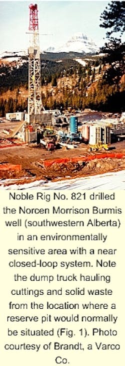
Obviously, the technology of dewatering continues to find a place in the drilling industry, with operators around the world modifying the NCLS to meet local needs (Fig. 1).
Anadarko
"We use dewatering systems in Canada to reduce surface disturbances and fluid (consumption) where there are limited water supplies," said Gordon Kristensen, drilling superintendent for Anadarko Canada Corp. in Alberta. "We also use it to reduce formation damage and control mud weights."
Drilling practices in Anadarko's Hayter field, in eastern Alberta near the Sasketchewan border, provide an excellent example of this system in which drilling intervals encompass three hole sections:
- Surface hole section-drilled with a bentonite slurry.
- Intermediate hole section-drilled with water.
- Horizontal production interval-drilled with expensive oil-base mud (light diesel).
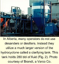
NCLS operations in this field utilize a different configuration of solids control equipment than what is found in the US. "In Canada, we rarely use desanders or desilters," said Todd Iverson, technical marketing representative for Brandt (a Varco Co.). "Instead, we use a clarifying tank, which is basically a massive hydrocyclone (Fig. 2)."
This tank, sometimes called a "concentrating conical tank," holds 280 bbl of fluid and can process up to 3 cu m/min. Thus, it can ably handle the mud-pump fluid rates while overflowing clear water, with a specific gravity of 1.0 to 1.01, back into the active system (Fig. 3).
Configuration
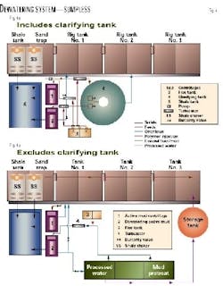
The NCLS consists of four solids control components (Fig. 4):
- Single or dual shale shakers.
- Clarifying tank.
- Polymer-flocculation unit.
- Centrifuges.
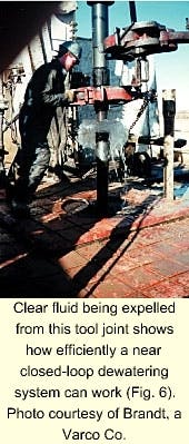
This equipment serves two purposes. First, it can be set up for solids control to remove drilling fluid waste according to particle size or specific gravity (Fig. 5).3 Second, it can be set up to dewater, or completely separate solids from the drilling fluid (Fig. 6).
The use of all components in the dewatering process, or only certain components for solids control, depends on the hole section and type of drilling fluid.
For example, because the well is spudded-in with clean water and because the surface hole section does not require high water volumes, drilling personnel typically use only shale shakers and centrifuges for solids control.
However, "After we run surface casing and wait for the cement to set up, we use the flocculation unit to return the used dirty drilling fluid in the tanks back into clear water," Iverson said.
Intermediate hole
During the intermediate hole section, the full complement of equipment, however, is used for continuous dewatering, unless it becomes uneconomic to use the clarifying tank.
"If the total well depth is less than 800 m, transporting the clarifying tank out to location may be cost prohibitive," Iverson said. "In this case, the centrifuges may be set up to handle the entire drilling-fluid flow rate through the active system."
In a situation where the clarifying tank is used, mud returns are processed over the finest screens that the shaker will handle, typically in the range of 60 to 75 mesh on Anadarko's Hayter operations.
Then the aggregate particles and larger drill cuttings can be vibrated off the shakers into a storage bin as the screened mud returns to the shale-shaker compartment. At this point, more coagulants and flocculants are added to the drilling fluid prior to being pumped into the clarifying tank, typically within the shale-shaker compartment.
"We often bypass other compartments in the (removal) system," Kristensen said, "further saving on drilling fluid volume."
Much like a desander or desilter cone, but on a larger scale, the clarifying tank then separates solids from water through the underflow of the hydrocyclone and recycles clear water through the overflow.
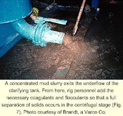
Thus, as the drilling fluid proceeds through the clarifying tank, the clear-water overflow is routed to the mud-pump suction tank while the solids underflow proceeds to two decanting centrifuges.3 Flocculants are then again combined with the underflow prior to being fed into the centrifuges (Fig. 7).
The centrifuges then discard the ultra-fine solids into the storage bin and returns the clean effluent to the additions section. If the clarifying tank is not used, two decanting centrifuges continuously process the fluid. In this case, the addition of flocculants takes place in the mud tanks with a direct line fed into the centrifuges.
"Flocculant is added just as the fluid enters the centrifuge, enabling the majority of the solids to be removed from the fluid while returning clear water to the tanks," Iverson said. "The only disadvantage to this process is that it is slower because the volumes of processed fluids depend on the size and type of centrifuges used on site."
Horizontal section
In the main and horizontal sections of the Anadarko operation, wellsite personnel next displace the clear drilling fluid with an expensive oil-base mud that uses a light diesel component. Similar to the surface-hole section, the NCLS is reconfigured for solids control by reducing ultra-fines through a batch process of regular dewatering.
"During this interval, it is important to control the oil-water emulsion through more standard solids control techniques as it is impossible to use the dewatering process in oil-base mud," Iverson said.
Unfortunately, because drilling and circulation rates are slower through this interval, ultra-fine solids will build up in the drilling fluid. To overcome this problem, one high-speed centrifuge remains entirely devoted to the active drilling fluid system. The second centrifuge, however, alternates between dewatering and solids control activities.
For dewatering, drilling fluids are transferred to a processing tank, pilot tested, pretreated with dewatering chemicals, and then batch processed through the centrifuge.3 These fluids are then used as make-up fluid for the active system.
Once the batch process is completed, drilling personnel then quickly change the settings to handle higher flow rates and then place the centrifuge back on line with the active mud system.
References
- Astrella, L., and Wiemers, R.A., "Evaluating closed loop systems," SPE/IADC paper 35116, presented at the annual drilling conference held in New Orleans, Mar. 12-15, 1996.
- Robb, A.J., and Bety, T.D., "Waste management and minimization in the Hugoton field, southwest Kansas," SPE paper 35915, presented at the International Conference on Health, Safety, and Environment held in New Orleans, June 9-12, 1996.
- Matthews, T.P. "Maximizing the benefits of a dewatering system," presented at the CADE/CAODC Drilling Conference held in Calgary, Apr. 19-21, 1995.
- Halliday, W.S., Bray, R.P., and Youens, J.W., "Closed-loop operation using alternate dewatering technology," SPE paper 20461, presented at the 65th annual technical and exhibition conference, New Orleans, Sept. 23-26, 1990.
- International Association of Drilling Engineers, Shale shakers and drilling fluid systems, Gulf Publishing, Houston, 1999.
Coagulation and flocculation. . .
Dewatering technologies, currently in use by the drilling industry, were adapted from the waste treatment sewage, mining, and industrial sludge industries.4
While there are several alternative methods for dewatering, including vertical screw presses, horizontal belt-vacuum filters, belt presses, and decanting bowl centrifuges, most oil-field operators have moved towards polymer-driven coagulation and flocculation techniques that chemically recombine colloidal particles into larger aggregate particles.
Coagulation
Coagulants can be distinguished from flocculants according to molecular weight, or polymer chain length. Polymers with molecular weights between 5,000 and 200,000 behave as coagulants in water.5
Coagulation, or the process of chemically neutralizing colloidal matter in order to form small "floc" particles, typically initiates or aids the flocculation process. Most water-suspended colloidal matter carries a negative charge, and will not settle until this charge is neutralized.
Typical coagulants used in Canada include calcium sulfate (gypsum), calcium nitrate, aluminum sulfate (alum), ferric sulfate, and ferric chloride.
Coagulation of drilling fluid is usually achieved by following two methods alone or in combination with one another:3
- Addition of inorganic salt that destabilizes the drilling fluid integrity and conditions the solids for flocculation by forming micro-flocs.
- Addition of a cationic charged low molecular weight polymer organic coagulant that overcomes particle charges and conditions solids for flocculation by forming micro-floc.
Flocculation
Polymers with molecular weights greater than 500,000 act as flocculants.5 Essentially, these longer chains trap and enmesh small floc particles in the process of forming long floc particles. As a result, the flocculation occurs when smaller, neutralized particle are agglomerated as settleable flocs.
A flocculating agent, typically containing a 5% anionic charge, gathers together small floc particles by means of bridging and enmeshment to form settleable particles. Bridging results when the long polymer chains of the flocculant reach out and gather small floc particles.
Enmeshment results from the netting effected on the cross-linking polymer structure. This traps and retains the small floc particles and allows the floc size to grow.5 Powders are the most common form of flocculants, although solution polymers have become quite common followed by emulsions.
Constant chemical matching
In typical Canadian systems operated by Anadarko Canada Corp. and Brandt (a Varco Co.), flocculants are typically added at the following locations (Fig. 4), depending on whether the clarifying tank is in use or not:
- Shale shaker compartment or in-line prior to the clarifying tank.
- Underflow stream from clarifying tank prior to the centrifuges.
Unlike slurry waste at a mine or sewage treatment, where effluent properties remain fairly constant and treatments can be standardized, each time additives are added to the drilling mud, or the drill bit encounters a change in lithology, the solids-liquid chemistry is affected.3
Additionally, as the drilling fluids continue to be reused and dewatered, anions can build up in the active system to levels that may create difficulties for dewatering treatment and drilling fluid properties.
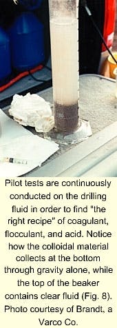
To counteract these changes so that effective flocculation continues to take place, wellsite technicians constantly "look for the right recipe," and so must constantly test the drilling fluid with an extensive selection of buffers, acids, bases, coagulants, and flocculants using pH meters, beakers, mixers, titration equipment, and scales (Fig. 8).
Thus, qualitative and quantitative treatment procedures can be obtained quickly without experimenting on large volumes of drilling fluid or unnecessarily mixing chemicals in the processing tank.
