Yukos, Big E employ near closed-loop systems
SOLIDS CONTROL-2
Drillers can eliminate most drilling fluid wastes, decrease the need for dilution, and reduce the cost for mud preparation with near closed-loop systems (NCLSs).
Yukos Oil Co., Moscow, which has adapted seven Siberian rigs to include centrifuges and flocculation-coagulation units, and Big E Drilling Co., Houston, which has constructed a new rig with a purpose-built system, show clear examples of how solids control systems can be tailored to accommodate local drilling practices.
System design
For most drilling rigs, solids-control equipment design must consider the following sections:
- Removal section-sand trap, degasser, desander, desilter, centrifuge, and flocculation unit.
- Onsite cuttings and fluid dump-reserve pit.
- Additions section-agitators, hoppers, and mud guns.
- Suction and testing section-suction tank, agitators, slug tank, and trip tank.
- Wellbore section-borehole, drillstring, casing, and drill bit.
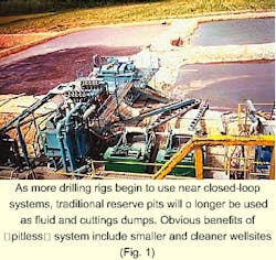
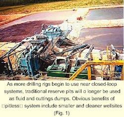
With an NCLS, however, the reserve pit, basically a large excavation lined with plastic (Fig. 1), has been entirely removed. Instead, drillers continuously remove cuttings in the removal section, then reprocess the waste-free effluent in the additions section.
From here, the reclaimed drilling fluid undergoes final preparation in the suction and testing section so that it can be recirculated back into the borehole.
Concurrently, waste solids, extracted in relatively dry form, are continuously collected and transported during the drilling operation for off-site treatment and disposal. Systems set up to discard these cuttings include augers, positioned near the sand trap for continuous conveyance of the cuttings, cuttings containment boxes, cranes, and dump trucks.
Removal section
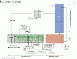
In many systems that include a full complement of NCLS equipment, drilling contractors arrange mud-tank compartments in a linear fashion so that shale shakers, degassers, desanders, desilters, centrifuges, and coagulation-flocculation units can be arranged sequentially, each with a dedicated tank (Fig. 2).
In this way, solids are treated from one tank to the next in order of diminishing particle size (see box: Near closed-loop system).
Thus, with a properly designed removal section, each piece of equipment will discharge fluids into the next compartment downstream of its suction compartment.
"No mud should enter the suction compartment in the removal system," said Mark Morgan, technical service manager for Derrick Equipment Co., "except directly from equipment immediately upstream or from an equalizing backflow. In this way, you won't mix dirty and clean fluid together."
To implement an efficient solids-control fluid path properly, each compartment, excluding the sand trap, should be set up so that drilling fluids flow backward from the downstream compartment into the upstream compartment (Fig. 3).1
"Backflow occurs by processing more fluid through the solids-control equipment than what is being circulated by the rig's main mud pumps," said Michael Richards, manager of applied technology for Brandt in Houston (a Varco Co.).
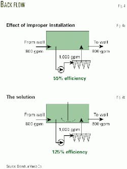
For example, if a desander is set up to handle 1,000 gpm and the mud pumps are processing 800 gpm, as the outflow from the desander exits into the desilter compartment, a reverse flow will occur from the downstream desilter compartment to the upstream desander compartment (Fig. 4).
Richards says that the equipment should process between 110 and 125% of maximum circulation rate to achieve an appropriate process rate with some capacity to spare.
Equalizers
To promote efficient circulation within the removal section, all of the compartments, except the sand trap (Fig. 2, Compartment 1) and dedicated degasser suction compartment (Compartment 2) should use bottom-mounted equalizers that connect one compartment to the next (Fig. 3).
These equalizers, typically 8 to 10-in. in diameter, play an important role in the backflow process, promoting efficient fluid circulation among the compartments so that all of the fluid can be processed.
"If you don't bottom-equalize, you run the risk of settling solids out in the desander or desilter tanks instead of passing all of the fluid through the equipment," Richards said.
In the last compartment of the removal section, an L-shaped adjustable stabilizer, usually fabricated with 133/8-in. casing, serves to connect waste-free effluent to the additions section.
In this way, the upper end of the stabilizer can transfer fluid as needed to the additions section, allowing personnel to control pit volume.
Additionally, every compartment, excluding the sand trap, should use agitators to maintain fluid consistency.
Problems
"The most common problem on drilling rigs consists of inadequate routing within the removal system," Morgan said. "When a substantial portion of the drilling fluid bypasses a piece of solids control equipment, all of the solids cannot be removed."
Some of the major problems in the removal section include unnecessary manifolding of centrifugal pumps, improper mud-gun use (stirring), leaking valves, and incorrect routing through mud-tank bypass troughs.
Morgan strongly believes that each piece of equipment should be fed with a dedicated, single-purpose pump that contains no "routing options." For example, if one centrifugal pump serves two pieces of solids-control equipment, head loss will increase and flow rates will decline through frictional losses associated with added pipe sections, elbows, and splits.
For example, a 6-in. line that includes two butterfly valves and one welded-branched tee can add the equivalent of 36 ft of 6-in. pipe to the overall length of the pipe connected to a centrifugal pump.1
Or the addition of an unnecessary 8-in., 90° welded "L" can add the equivalent of 55 ft of straight pipe in terms of frictional pressure loss. "This can cause serious problems if you don't correctly calculate the head, friction loss, and pump flow rates," Morgan told a solids-control class last June.
Additionally, shared pieces of equipment (i.e., centrifuge and desilter) will almost certainly require different outputs. Thus, you may be locked in by the original configuration of the pump's impellers, motor speed, and horsepower, which may not be matched for both pieces of equipment.
This has obvious implications when it comes to arranging pump suction and overflow discharge locations and can produce conditions of pump cavitation (destructive formation of vapor bubbles in the centrifugal inlet) and the settling of solids in the pipe.
Additions section
By the time the processed wellbore fluids reach the additions section, all of the solids have been removed. At this point, however, the clean fluids must be reformulated with chemicals to produce the required drilling mud.
Additionally, as drilling continues, newly drilled hole requires new drilling-fluid volumes to compensate for the growing hole volume. Otherwise the tanks will run dry (OGJ, Aug. 21, p. 31).
To mix chemicals such as barite, polymers, and bentonite in with the mixture of recycled wellbore and newly added fluids, a hopper is set up to draw from the downstream compartment (Fig. 2, Compartment 8). In turn, these chemicals are mixed within a high velocity jet stream that is expelled into the upstream compartment (Compartment 7) or into the slug tank (Compartment 11).
To produce a homogeneous blend, the tanks are constantly agitated and stirred with agitators and mud guns.
Suction section
The suction portion of the solids-control system forms the last section of the surface system.1 At this point, there must be enough useable fluid to keep the mud pumps primed and the hole full. And again, agitators and mud guns should be used to maintain a consistent blend.
To ensure a properly treated drilling mud, mud engineers or derrick personnel will test the mud for rheological properties at the mud-pump suction compartment (Fig. 2, Compartment 11), prior to being pumped downhole.
Additionally, a small slug tank (20-50 bbl) is used to spot lost-circulation material, heavy pills for trips, and special treatments. This compartment, which is manifolded to a hopper, however, is isolated from the active mud system.
Finally, a mud-tank system will also include a calibrated trip compartment that measures the volume of fluids leaving and entering the hole while tripping in and out of the hole with the drillstring or casing. These volumes are monitored as a check for hydrocarbon entry that can be caused by swab-and-surge pressures.
When one barrel of steel is removed from the borehole, one barrel of drilling fluid must replace it to keep the hole full.1 Otherwise, the liquid level may drop, with a resulting loss of hydrostatic pressure that can lead to formation fluid entry or a collapsed borehole.
Excess fluid returned to the trip tank from the hole should be reprocessed through the removal section because it may contain hole cavings and other contaminants.
A Russian system
Whereas some companies have been slow to update mud pit and equipment design, instead relying on simple arrangements of shale shakers, settling compartments, and reserve pits to meet their solids-control needs, supposed "backwater" companies like Yukos and Lukoil (OGJ, Nov. 24, 1997, p. 53), Moscow, have ironically taken advantage of modern solids-control technologies.
Priobskoye field
Russian major Yukos provides an excellent example of a system upgrade fitted for seven Siberian Uralmash rigs operating in the Priobskoye field of the Khanty-Mansiyski Autonomous Okrug.
To overcome the swampy conditions along the Ob River, these rigs, operated by Nefteyuganskburneft, move on rails from well-to-well in a "cluster-type pattern." Not only does cluster drilling reduce the environmental impact, but also the company gains operational and cost benefits from obvious moving and logistical efficiencies.
Typically, Yukos drills 8 to 16 wells along each cluster, spaced about 5 m apart. "The idea is to drill as many wells on each cluster, with two rigs in parallel [Fig. 5], so we can reduce the number of pads, roads, and so on," said Yevgeny Rykov, deputy director for Yukos Exploration & Production.
To position all wells optimally within a reservoir, Siberian drillers employ S-shaped well configurations to target various portions of the pay zones along the cluster. Typically, surface casing is drilled on the first well of the cluster using water-base mud formulated with bentonite and chemical additives.
Subsequently, this mud is reused well after well until the cluster is finished, taking advantage of the solids control equipment.
Once surface casing is set, Yukos initially drills out with water. Then, as dictated by the formations, drilling crews add bentonite and other additives to maintain a fluid weight of 1.14-1.16 sp gr until TD is reached at 2,800 m.
System design
According to Vladimir Paltsev, chief engineer for Yukganskneftegaz (local subsidiary of Yukos), the company began looking into modern systems during the early 1990s. "By mandate, we have to protect the Ob River from environmental damage," he told OGJ during a field visit to Priobskoye, "thus, we had to build a solids-control system that was as close as you can get to a closed loop."
Basically, these rigs employ two shale shakers, desanders, two centrifuges, and coagulation-flocculation units as described above, except that the L-shaped configuration of tanks has been replaced with a more compact design.
"We had to install an additional module on the Uralmash rigs," Rykov said. "This was no easy task as we had to use a design long-adapted for Siberian drilling conditions, and reconfigure it so that the solids are properly treated along the system."
Engineering oversight has fallen to Yuganskvishkomontazh, a company that was divested by Yukos during its restructuring program in the late 1990s (OGJ, June 14, 1999, p. 21).
This company, under the guidance of Rykov and its president, Vasi* Galaevski, chose to utilize equipment provided by Derrick Equipment Co., Houston, and Oiltools Europe Ltd., Aberdeen.
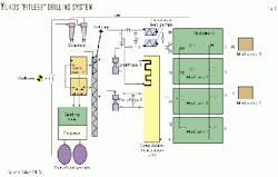
The solids-control system includes shale shakers and desanders installed in series and centrifuges installed in parallel to the drilling-mud circulation system (Fig. 6). As the drilling fluid and cuttings exit the wellbore, they flow through the flow line and onto the shale shakers.
"Particles that exceed 100 mm in diameter are then sent to a cuttings transporter, conveyed by an auger, while the remaining fluids and cuttings fall through the shaker screens into the mud-settling tank," Rykov said.
"Typically, the moisture content of the cuttings downstream of the shakers varies from 40 to 70% by volume, depending on the rock type." For example, moisture content may be 40 to 60% for sandstones, 50 to 70% for high-colloidal clays, and 35 to 50% for argillites and siltstones.
"This is why we call it a 'near closed-loop system,' in that it is not economically practical to remove all of the moisture from the cuttings, especially during fast drilling conditions," he said. "Due to problems with swelling shales, we have to finish the well rather quickly or we'll have problems with the hole closing in."
From the mud-settling compartment (sand trap), the drilling mud is then passed through the degasser and desanders to Mud Tank 2. Simultaneously, solids that exceed a moisture content of 50% are redirected towards the shale shakers again, then vibrated onto the cuttings transporter (auger).
"If the specific gravity of the drilling mud in the circulation system exceeds that which is specified in the work plan, the drilling crew will turn on the centrifuges and process the drilling fluids that have passed through the desander," Rykov said.
From the centrifuges, "the pulp," with a 45-50% moisture content, is then delivered to the cuttings transporter and the treated drilling mud is sent back into the active mud system.
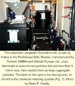
"If the drilling-fluid gravity varies by 0.02 g/cc between the drilling mud upstream and downstream of the centrifuge, we will treat the fluids with flocculants, coagulants, and acids to achieve a better separation of the solid phase (Fig. 7)," Rykov said.
In this way, very small particle sizes can be recombined to form large particles, then expelled from the drilling-fluid system.
According to Steve Zagdan of Oiltools Europe Ltd. (Aberdeen), who has been directly involved with Yukos in designing the solids-control system, the flocculant mixing technology is specially designed for arctic conditions.
Basically, it incorporates two tanks where mixing is performed on each tank in batch mode. As soon as one tank is ready for dosing, the suction and discharge lines are then switched, allowing the second tank to be prepared.
A specialized nozzle and mixing system ensures an homogenous solution. This solution is prepared from granulate or powder and can be adjusted for the required maturing period depending on the types of materials.
At the end of the maturing period, the solution is then passed through the centrifuges where the fluid is separated into service water (0.5% solid phase), which is then supplied to any of the mud tanks, and the cuttings (50-60% moisture content) are directed to the transporter.
Big E Drilling Co.
Big E Drilling Co., Houston, provides another example of a NCLS, but specifically designed for a new build-Big E Rig No. 5 (OGJ, Aug. 14, p. 58). This 1,500-hp rig, rated to 20,000 ft, operates in South Louisiana and Texas within the coastal and wetlands areas near Beaumont.
"In the Gulf Coast area, most of the rigs use closed loops because of the wetlands," said Lyle Eastham, contracts manager for Big E. The US Environmental Protection Agency guidelines "are getting more stringent in these areas, forcing us to move in this direction."
Environmental concerns are only part of the motive, however. "The costs needed to build a reserve pit, maintain it, then return it back to its former state can be much greater than the costs of employing these technologies," said David Largent, technical service manager for Brandt.
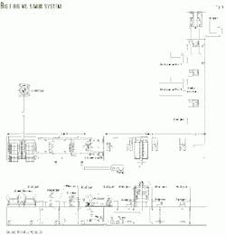
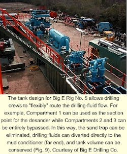
As compared to the solids control system shown in Fig. 2, Rig 5's compartment layout varies from many designs in two ways. To begin with, the first compartment of Tank 1 (Figs. 8 and 9), traditionally used as a sand trap, can also serve as the suction point for two 12-in. hydrocyclones (desander).
Thus, the traditional function of a sand-trap compartment, which requires periodic dumping, can be eliminated so that the total waste volume for the well is reduced. "Solids that would normally settle in the sand trap are instead captured by the solids-control equipment," Largent said.
Second, fluid flow can be sequentially routed and treated through the desander, desilter, degasser, and mud conditioners, or "flexibly" routed from compartment to compartment so that certain compartments are circumvented, depending on the situation at hand.
"When we drill with oil or synthetic-base mud, we can bypass the desilter compartment if needed, saving on costly fluid volume," said Ronnie Latham, drilling superintendent for Big E. Or, if gas-cut mud is encountered, the drilling fluid can be directly diverted to the degasser through a shale shaker trough.
The degasser can then draw suction from Compartment 3, process it through the degasser, then discharge the gas relieved fluid into the first compartment of Tank No. 2 (fourth compartment of the entire system). Equalization between Compartment 3 of Tank 1 and Compartment 1 of Tank 2 is accomplished by means of a high overflow pipe.
"One danger when processing gas-cut mud between compartments is equalizing at a low point," Richards said. "Basically, differences in mud density before and after degasser processing can cause a stagnant upstream compartment, or if the density difference is great enough, can cause the upstream compartment to overflow the tanks." By equalizing at a high point as Big E does, this danger is eliminated.
Rig No. 5 is also set up to include additional solids control equipment such as centrifuges and flocculation units.
Reference
- International Association of Drilling Engineers, Shale shakers and drilling fluid systems, Gulf Publishing, Houston, 1999.
Near closed-loop system
The following describes the setup for a commonly used NCLS (Fig. 2):
Tank 1. Separate solids from the mud through the use of shale shakers positioned above the sand trap. Fluid flow proceeds downstream over top of weir into degasser tank.
Tank 2. Remove entrained gas with degasser so that centrifugal pump operation is not disrupted and so that bubbles are removed from drilling fluid. Because the output from the degasser into Tank 3 is greater than the mud-pump circulating rate, backflow occurs from Tank 3 to Tank 2.
Tank 3. Use desander to remove sand-sized particles, or drilled solids not removed by the shale shakers. The desander should be placed upstream of the desilter. Because the output from the desander into Tank 4 is greater than the mud-pump circulating rate, backflow occurs from Tank 4 to Tank 3.
Tank 4. Use desilter to remove silt-sized drilled solids not removed by the shale shakers and desander. Because the output from the desilter into Tank 5 is greater than the mud-pump circulating rate, backflow occurs from Tank 5 to Tank 4.
Tank 5. Use centrifuge to remove ultra-fine and colloidal particles. If needed, adapt centrifuges to also retrieve barite and other colloidal chemicals.
Tank 6. Use coagulation-flocculation unit to recombine colloidal particles into larger aggregate particles. Remove the flocculated solids with a centrifuge and discard aggregate particles along with shale shaker cuttings. Advance free water to the additions section for drilling fluid preparation (Tank 7).
In addition to the above setup, however, there may be variations based on whether the operator requires weighted drilling fluids, water or oil-base mud, synthetic-base mud, barite retrieval, and so on.
Also, tank configurations for legacy systems may force drilling contractors to make adaptations within the confines of smaller drilling units and so on.
