Modern technologies provide environmental, economic incentives
SOLIDS CONTROL-1
Modern solids-control technologies, when applied correctly, can reduce environmental wastes, lower drilling fluid and disposals costs, prevent stuck pipe, improve penetration rates, and reduce drill-bit wear.
Worldwide, operators and contractors use three basic arrangements to remove drill cuttings, control mud weight, and maintain rheologic properties. These are:
- Simple earthen pits lined with a zig-zagging arrangement of dikes. Gravity is used as the primary means to drop out sediments, and natural clays are used as a weighting agent.
- Mud-tank arrangements that process drilling fluid sequentially and combine mechanical and settling techniques to reduce drilled solids while controlling fluid properties. These systems continue to use reserve pits, or secondary earthen pits, as a cuttings and fluid dump and source for dilution.
- Near-closed-loop, or "pitless" systems with sequentially arranged mud tanks, shale shakers, hydrocyclones, centrifuges, and flocculation-coagulation units. Earthen and reserve pits have been eliminated, as drilling fluids are continuously recycled. Fluids are cleaned down to the sub 5-mm range.
While earthen pits are becoming obsolete, the second configuration remains the dominant arrangement in use today. On another front, however, pitless drilling technologies are making headway in environmentally sensitive areas such as river plains and coastal areas found in Siberia, South Louisiana, Jakarta, Singapore, Venezuela, and Argentina.
The government let a contract for 10,000 sq km of exclusive multicomponent 3D seismic surveys in advance of a deepwater licensing round.
Eliminating solids
According to Mark Morgan, technical service manager for Derrick Equipment Co., Houston, the proper installation and plumbing of solids-control equipment must be integrated into the rig.
"The primary goal is to knock solids out of the system as quickly as possible. Otherwise, drilled solids will erode, disperse, and break down into smaller and smaller sizes as they travel throughout the mud system."
This process of disintegration has a detrimental effect on viscosity, rheology, bottomhole assembly (BHA) torque and drag, wellbore environment, and fluid hydraulics.
For example, if a single cube (representing a cutting), with a total surface area of 6 sq in., is split in half, the surface area will double. Yet if the original cube is split eight times, the surface area will grow to 1,536 sq in. Accordingly, this growth in surface area will allow solids to absorb more free fluid, affording a proportional increase in viscosity.
The effect of cuttings breakdown on viscosity can be shown by mixing a cup of whole-grain wheat in 1 quart of water, then separately mixing the same amounts of ground flour in water. "The wheat and water, when stirred, would move almost the same as before the 'large' grains of wheat were added," Morgan said. "The viscosity would be almost unchanged."
Yet if the same amount of wheat were ground to flour, then added to the water, the resulting dough would be many times thicker than the wheat and water. In this case, the total amount of solid added for each sample remains the same, but the effect on viscosity becomes quite different. "Thus, a solids problem can occur without an increase in solids content, Morgan said."
Then taking into account the reactive properties of lithologies (i.e., sandstone, limestone, anhydrite) and the reactive properties of various drilling fluids (i.e., polymers, synthetic-base mud) makes the problem even more convoluted.
Thus, if smaller solids are not removed from the system before they enter the borehole, thick and soft filter cakes can build up on the wellbore wall. Subsequently, this filter-cake buildup can:
- Increase torque and drag on the drillstring.
- Increase contact between the drillstring and borehole to promote stuck pipe situations.
- Increase formation damage.
- Force cement to "channel" around mud-cake buildup, resulting in a partially and poorly cemented wellbore.
- Promote swab-and-surge pressures while tripping pipe.
Finally, the buildup of colloidal particles can slow penetration rates.
Methods of solids control
Three common methods of solids control are used in the industry today:
- Gravity and settling.
- Dilution.
- Solids removal equipment.
The first technique, as explained above, has been applied most commonly in earthen pits and should not be used. Basically, gravity does not effectively remove colloidal and silt-sized particles as the basic fluid properties will continue to entrain sediments for indefinite periods of time.
Dilution, however, can be extremely effective but must be properly applied. For example, drillers can eliminate half of the drilled solids by dumping half of the system with an equal replacement of fresh fluids. This is an expensive process, however, as the displaced fluid must be restored.
Dilution
To analyze the appropriate need for dilution, Robinson examined a surface system that contains 1,000 bbl of drilling fluids with a targeted drilled solids level of 4% by volume after processing.2 In the first of three examples, two explained below, he assumes that 100 bbl of drilled solids come to surface through the drilling process where a 10-in. bit drilled 1,000 ft of formation.
First, he targets a system in which the solids-control system removes 100% of the cuttings. In this case, there is no need for dilution as all the solids are removed with efficient solids-control equipment.
But because 1,000 ft of formation has been drilled, an additional 286 bbl of fluid will still be needed to maintain constant pit levels; otherwise the pits will dry up.
In another scenario, the operator desires only 80% solids removal efficiency in which 80 bbl of solids are removed by the solids-control equipment and 20 bbl are returned to the pits. This situation requires 229 bbl additional fluids to compensate for the newly drilled hole.
Yet diluting 20 bbl of returned solids to a 4% drilled solids concentration will also require an additional 271 bbl of drilling fluids. Of course, this is slightly offset by the 20 bbl of solids that have been returned to the system, but in the end, the operator will need 480 bbl of new fluids for every 1,000 ft of hole drilled (229 + 271 - 20 = 480 bbl).
Unfortunately, as these additional fluids are added through dilution, total volume will continuously build up and must be disposed of.
Economic incentive
"By looking at the cost-to-benefit relationships, we can come up with some interesting conclusions," Morgan said. "In most cases, we can save enough on just the costs of dilution, mud additives, and disposal to justify the cost of the best solids-removal equipment available."
For example, maintaining a mud weight of 9.0 ppg or 5% by volume content of drilled solids, with a target removal rate of 70% for the drilled solids, requires about 5.7 bbl of dilution per barrel of drilled solids.1
Assuming a 121/4-in. bit drilling at 50 fph over 24 hr, 175 bbl of cuttings will be removed from the wellbore. But with a 70% removal rate, dilution could exceed 998 bbl.
Using improved solids-control equipment, however, and improving removal efficiencies by just 10% mean that only 665 bbl of fluid will have to be added to provide the required dilution. "This could be a savings of 1.9 bbl of dilution for each barrel of hole drilled," Morgan said.
Considering a conservative cost of $8/bbl for fresh water-base drilling mud, the drilling contractor and operator would then save $2,656 in a 24-hr period. And with synthetic-base mud running more than $100/bbl, the cost-to-benefit ratio becomes readily apparent.
Additionally, this does not consider waste-disposal costs, the effect on penetration rates, and wear and tear on the mud pump.
Solids-removal equipment
The primary types of solids-removal equipment include shale shakers, hydrocyclones (desanders, desilters), mud cleaners, and centrifuges.
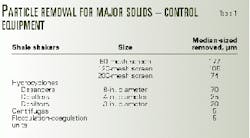
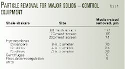
Shale shakers are the first piece of equipment that drilling fluids and cuttings encounter once they exit the wellbore. "Shale shakers should be designed to use the finest screen possible, with the least loss of whole mud (Table 1)," Morgan said. In this way, fine-grained solids are immediately eliminated and do not have an opportunity to degrade.
Shale shakers work through a screening process where the fluids and cuttings flow onto a vibrating square panel. The screen opening, or mesh size, determines the size of particle that will be filtered.
In the petroleum industry, the three most common types include 80, 120, and 200-mesh screens. These screens are designed to remove median size particle of 177, 105, and 74 mm, respectively, under optimal conditions.
"Selection of a screen is a compromise between solids removal, circulation rate, and the life expectancy of the screen," Morgan says.
When screens are used with a liquid, a high surface-tension film forms on the wires. This film reduces the effective opening to some value smaller than the mesh would indicate and increases as mud viscosity increases.2
Shaker motion
The type of motion, stroke length, and motor rpm define the performance parameters of a shale shaker where travel direction of the cuttings and speed on a horizontal deck depend on the direction of rotation, the frequency of vibration, and the amplitude of motion. "If for some reason the cuttings are just sitting there, not moving, something is wrong," Morgan said.
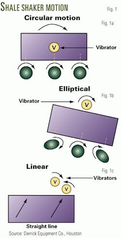
There are four types of shaker motion. First, if a single vibrator is mounted close to the screens and center of gravity, the motion forms a circular pattern (Fig. 1a).2 Second, if a single vibrator is mounted above the center of gravity, the motion forms an elliptical pattern at the ends of the deck but remains circular below the vibrator (Fig. 1b).
In this setup, the axis of the ellipse, screen slope, and direction of rotation control the travel rate of the solids. Typically, these shale shakers have divided decks with screens placed at different slopes in order to provide proper cuttings discharge, or the screen deck is tilted in a downhill position.2
A third type, the linear-motion shaker (Fig. 1c) uses two equal-mass vibrators rotating in opposite directions and mounted in parallel.1 Screens can be run uphill with the screen slightly inclined towards the wellbore. The travel rate of the cuttings depends on the slope of the motion axis, screen slope, stroke length, and vibration frequency. "With linear motion," Morgan said, "there is no wasted energy as the cuttings are conveyed directly off the screen."
Finally, balanced linear motion shakers consist of two vibrators, of unequal masses, rotating in opposite directions and mounted in parallel. With this device, the ellipse aspect ratio (major to minor axis), is controlled by varying the angle between the vibrators.1
Shale shakers can utilize single or multiple screens where separation is determined by the finest, or bottom screen (Fig. 2). The coarsest screen should always be placed on top. Another variety of screen type, not discussed here, includes convex screens and screens that have been molded with peaks and valleys along the longitudinal axis of the shaker.
Hydrocyclones
Rig personnel must understand the principles behind hydrocyclone theory, as improper adjustments can produce solids-removal inefficiencies.
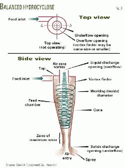
Hydrocyclones, which consist of desanders and desilters, form the second line of defense in most solids-control applications. These devices consist of a cone containing a feed inlet, solids-discharge opening (underflow), and liquid discharge opening (overflow, Fig. 3).
Desander cones are typically 6 in. and larger and remove particles on the order of 70 mm. Desilter cones are typically 4 in. and smaller and remove particles down to 5 mm.
The feed opening for these devices is positioned at the top end of the cone perpendicular to the feed chamber wall. The feed opening can be involute or tangential. Involute flow is produced through a circular feed inlet shaped so that the flow remains turbulent for a longer period of time.
"Tangential flow, on the other hand, comes from a rectangular inlet, which reduces turbulence, resulting in increased separation efficiency," Morgan said.
Operation
During operation, a feed slurry of solids and liquids is fed through the inlet at high speed, obtained by a steady pressure or feed head.2 This force creates a spinning velocity that produces the centrifugal force. Centrifugal force and inertia cause the solids to settle outward toward the hydrocyclone wall, in the downward spiraling stream.
Solids then separate according to the weight and size of the particles. As the cone narrows, inner layers of the downward spinning liquid turn back toward the overflow, a result of the increasing centrifugal forces located near the center of the cone.
For a balanced design, as the latter portion of the liquid moves to the center and back up toward the overflow, the downward spiraling solids continue out the underflow, unable to turn back because of their greater inertia and high downward velocity.
The solids that spiral downward concentrate through a process of outward settling, aided by the narrowing design of the cone towards the end. If the cone is balanced, and if there are not too many solids by volume in the downward spiraling stream, the spray underflow will appear much like that shown in (Fig. 3), except the particles travel so fast they sometimes give the appearance of a shower head.
The liquid film will vary from 90% of total volume underflow when only very fine solids are separate to 50% when only coarse sand is removed.
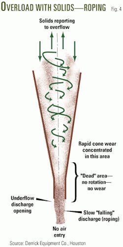
When the solids load becomes heavy, as in a fast-drilling situation, there may not be room for all of the downward moving solids to exit the underflow discharge port (Fig. 4).
Instead, the solids slow down in the dead area near the exit, and the total portion to be separated becomes severely reduced. "In this 'rope-type' discharge, the liquid volume will be about 50% of the total, sometimes less," Morgan said.
Subsequently, solids that cannot exit the "rope-type" underflow will immediately be swept up the center stream to the overflow. This stream will include almost all of the smaller and lighter solids because only those with the greatest mass will find their way out the underflow.
As most hydrocyclones contain underflow opening adjustments, it is relatively easy to maintain a balanced spray by adjusting all the cone bottoms at one time until each drips, then leaving them alone. Then if the cones become overloaded, drilling personnel can simply open the apex until the drip resumes.
Unfortunately, hydrocyclones tend to plug easily, especially with trash and rubbish ever present in a drilling operation. Fortunately, hydrocyclones are easy to remove and clean out by shutting a valve and removing a snap ring.
Centrifuges
Centrifuges, which typically work in the 10-15 mm range but under the right conditions remove solids down to 5 mm, process drilling fluids in two ways.
First, they can remove solids from an unweighted mud while returning the liquid phase to the active system. This helps to control the weight or density of the mud. Therefore, the liquid phase containing colloidal solids such as bentonite and chemical additives can be returned to the active mud system.
Second, centrifuges can be used to return solids to the active system while discarding the liquid phase. "In this way, you control the rheologic properties of the mud by removing colloidal particles (clay, barite, and drilled solids that have degraded), then replacing this with clean-based fluid," Morgan said.
"You are not just per se recovering barite; you can also put larger particles in the silt-sized range back into the system while getting rid of the clay-sized (colloidal) particles with the effluent."
Construction
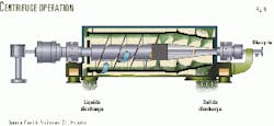
A centrifugal pump consists of a rotating vane, or impeller, installed within a chamber (Fig. 5). "Basically, it is just a tank wrapped around a conveyor," Morgan said. However, both the auger and the outer wall (tank) move independently of each other, in the same direction, but at different speeds.
The performance for a given mud depends on the g forces exerted on the fluid, mud-retention time in the centrifuge, and conveyor differential. The items which can be manipulated in a centrifuge operation include feed rate, dilution, gear ratio (by changing the gear box), pool depth (by changing the weir settings), and rotational speed which changes the g force.2
Because a centrifuge operates on the principle of accelerated settling, Stoke's Law can be applied. Consequently, if a sphere settles in a liquid of known density and viscosity, and the settling rate is measured, it is possible to configure the centrifuge so that same sized particles, with different specific gravities, will separate according to the need.
As a result, heavier particle like barite will settle faster than other clays by using a deep bowl depth, a high conveyor speed, and low g's.
References
- Robinson, L., "How to optimize solids control economics, efficiency," Petroleum Engineer, September 1994, pp. 17-24.
- Morgan, M., Derrick, solids control manual, published by the author, September 1998.
- International Association of Drilling Engineers, Shale shakers and drilling fluid systems, Gulf Publishing, Houston, 1999.
