Operational changes fix FCCU catalyst loss problem
After experiencing a huge catalyst loss while bringing up one of its fluid catalytic cracking units (FCCUs), Sinopec's Shijiazhuang, China, refinery detected and isolated five leaking clusters from its FCCU external cooler.
The company successfully used a safer and quicker procedure, different from its traditional methods, to detect these leaking clusters.
Investigation revealed that improper maintenance during a long period of feed outage for the FCCU and improper operations were the main causes of the leaks.
Based on its experience, the Sinopec refinery has developed new procedures to isolate and repair leaking clusters. It has also developed recommendations to minimize the possibility of future cluster leaks.
After raising the catalyst level and adjusting other parameters, Sinopec is running its FCCU at design capacity with five isolated clusters.
FCCU design
The second resid FCCU (RFCCU) of Sinopec's Shijiazhuang refinery, called No. 2 FCCU, began operations in 1995.
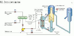
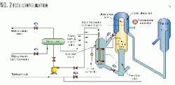
The Beijing Design Institute (BDI) designed the unit. The No.2 FCCU regenerator has a catalyst premixing tube with an external cooler (Fig. 1).
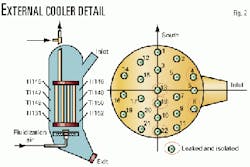
The No. 2 FCCU's external cooler (Fig. 2) is designed for 23 tonnes/hr of 35 kg/sq cm saturated steam. The external cooler removes heat from the regenerator to maintain the heat balance between the reactor and the regenerator. The shell side of the cooler has fluidized catalyst, and the tube side has water.
The waste heat boiler takes the saturated steam from the external cooler and from the slurry-steam generators. The boiler superheats the steam and sends it to the plant's medium-pressure steam system to power equipment, like the wet-gas compressor and the steam-powered generator.
The water from the external cooler can produce up to 30 tonnes/hr of saturated steam. Its typical water-circulation is 400 tonnes/hr for a 17:1 water/steam ratio (the design requirement is not lower than 14:1).
The catalyst side is designed for catalyst circulation rates up to 400 tonnes/hr, with typical rates on the order of 300-350 tonnes/hr.
This particular cooler has 22 clusters; each cluster has four tubes.
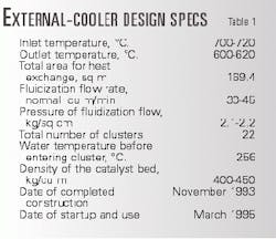
Table 1 lists other basic design parameters of the external cooler.
The unit is designed for 800,000 tonnes/year of Daqing and Huabei atmospheric tower bottoms (ATB). Typical feed to the unit is a mix of unhydrotreated Huabei, Erlianhaote, and Xinjiang ATB.
The Conradson carbon residue content of the feed is 4-6 wt %. The nickel content is 15-23 ppm, and the vanadium content is 0.38-0.70 ppm. Total metals on the equilibrium catalyst is 10,000-14,000 ppm.
The company maximizes the unit's throughput in the gasoline and LPG mode. Maximum feed rates are 2,600-2,900 tonnes/day.
Catalyst loss
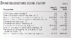
After a 2-year shutdown, Sinopec restarted No. 2 FCCU on June 3, 1999. The company detected nothing unusual, and increased the feed rate per normal start-up procedures. Table 2 shows the operating conditions during this period, as the feed Conradson carbon residue and regenerator temperature began to rise.
At the proper regenerator temperature, operators began to open the inlet slide valve of the external cooler.
On the next afternoon, without any warning, enormous amounts of catalyst suddenly spouted out of the stack from the final flue-gas outlet. An hour later, with approximately 50 tonnes of catalyst loss (equal to about 60 % of the catalyst inventory), Sinopec shut down No. 2 FCCU.
With the unit shutdown, Sinopec engineers and operators analyzed the operations to find the cause of the catalyst loss.
Engineers found some unusual operational data. First, the temperature differential of three dense-phase thermocouples among the same level was more than 4° C. This differential number should be no more than 0.5° C.
The northwest thermocouple was located near the external-cooler inlet and dense-phase fluidization-air pipe inlet. The varying regenerator temperature at the external cooler indicated that serious channel flow had formed.
The dense-phase bed level fluctuated by more than 4% during the catalyst-loss period; the normal range is no more than 2%.
Moreover, the catalyst density of the dense phase changed from the usual 400-450 kg/cu m to 550-600 kg/cu. Such high densities may be the result of water from the tube leaks meeting up with high temperature catalyst. This sudden temperature difference will damage the catalyst internal structure.
With the above discoveries, the Sinopec refinery narrowed the cause of damage to several possible pieces of equipment: the regenerator cyclones, the dense-phase catalyst pipe inlet, and the external cooler clusters. After inspecting the cyclones and the regenerator dense-phase catalyst pipe, Sinopec eliminated them from the likely cause of the incident.
On the northeast side of the dense-phase bed, the company found a lump of catalyst beside the cooler inlet. Upon opening the inlet slide valve of the external cooler, the inspectors found that two-thirds of the cooler was filled with water, verifying that there was a leak among the clusters.
Detection, isolation of leaks
The traditional way to detect and isolate leaking clusters in the external coolers involves at least two operators. The operators gradually close both the inlet and the outlet block valves at the same time, while observing the change of the inlet local pressure gauge.
If the pressure increases quickly, that set of cluster being tested is in good shape. If the pressure drops, the cluster set should immediately be isolated.
This traditional method has two shortcomings:
- The procedure is difficult and dangerous for the operators, because it is performed when the external cooler is in operation.
- It takes a long time to test every cluster in the external coolers.
Considering the above shortcomings and No. 2 FCCU's special situation, refinery personnel developed a new procedure to detect and isolate the leaks. The first three steps are the "cold-state test:"
- While the unit is shutting down, bring cool water in the external cooler to normal operating pressure.
- Isolate every cluster's inlet and exit valves and record the gauge values.
- After half an hour, check the 22 gauges. If the pressure has not changed or has dropped no more than 0.5 kg/sq cm, the clusters are not leaking. If the pressure dropped by more than 3 kg/sq cm, however, leaking clusters should be suspected.
- As the FCCU is restarted, look for fluctuations in the regenerator dense-phase bed or in the external cooler. If any fluctuations occur, immediately stop opening the cooler's inlet slide valve, stabilize the operation, and find the leaking clusters by methodically closing the inlet and exit valves. An increasing pressure drop indicates that cluster is leaking. Step 4 is the "heat-state test."
- After all of the suspected clusters have been checked and the leaking clusters isolated, return the FCCU to normal operating conditions.
With the above detection procedure, Sinopec isolated five leaking clusters: Nos. 4, 8, 13, 18, and 22 (Fig. 2). After isolating these five clusters, the catalyst loss immediately stopped.
Some damaged clusters did not leak in the cold-state test and leaked only when certain parameters were exceeded during the heat-state test.
During the cold-state test, taking advantage of the unit shut down, Sinopec opened the external cooler's bottom manhole. The company expected to find several water leaks here. There was not any water, however, even in clusters with a large pressure drop.
During the initial stage of the unit start-up, during the heat test, the serious catalyst loss did not occur until the inlet valve position was opened beyond 10% and the maximum temperature in the external cooler progressed beyond 400° C.
Like poor fluidization, symptoms of leaking clusters include temperature differentials above 4° C. and fluctuating bed levels. Unlike fluidization problems, however, leaking clusters experience the following phenomena:
- An obvious catalyst loss through stack.
- Instability of pressure differential of the catalyst cooler's exit slide valve.
- A sudden decrease in the temperature at different levels of the external cooler.
- A 2-3 min period during which the coke-burning tank temperature decreases by 3-6° C.
- Instability of the external cooler's level and density.
- The dense-phase bed fluidization is worse.
Leak causes
The simultaneous failure of five clusters is rare in the history of BDI-designed external coolers. Sinopec found four main causes of the serious cluster leak: lack of anticorrosion measures, partially open cluster-inlet valves, and operational difficulties.
- Lack of anticorrosion measures. From March 1995 to June 1999, Sinopec did not run the FCCU because of a refinery-feed shortage. During this period, No. 2 FCCU did not adopt anticorrosion measures.
The clusters and their parts are primarily made from carbon steel. If unprotected, water and oxygen can corrode the steel.
Sinopec should have adopted two measures to prevent the corrosion of the steel: First, it should have removed the air in the clusters by filling up the inner space of the cluster with 3-4 kg/sq cm of deoxygenated water.
Second, Sinopec should have passed nitrogen through the external cooler to protect the clusters' external surfaces, from corrosion by moist air.
Unfortunately, Sinopec adopted neither of the above measures, and moisture and oxygen corroded the clusters. Visual inspection of the clusters on Aug. 3, 1999, revealed corrosion trails on the surfaces of all the clusters and concentrated leak-damaged areas on the cluster bottom's connection box.
- Partially open cluster-inlet valves. During the start-up of the external coolers, the operators failed to fully open the inlet valves of some clusters.
After a careful check, Sinopec found that seven cluster inlet valves were not entirely open; most of their positions were not more than one third of the way opened. Five of these seven clusters leaked.
Poor water circulation also contributed to the lack of water supply to the external cooler, worsening the cluster leaks. The distributed control system (DCS) history-data record showed that only 220 tonnes/hr (vs. 500-600 tonnes/hr) of water circulation ran for 30 hours after the unit start-up.
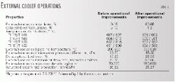
- Operational control difficulties. Table 3 shows the typical operational data of the external cooler before and after proper adjustment of the catalyst level. Before improvements initiated by Sinopec during the downtime, the catalyst level was low and its fluctuation was rather large.
Instead of controlling the catalyst level (and thus temperature) of the external cooler with the exit slide valve, as BDI had originally intended, the operators controlled it by throttling the cooler's inlet valve.
In its design, BDI meant for the operators to fully open the inlet slide valve of the external cooler and throttle the exit slide valve.
The external cooler is 6-7 m lower than the dense-phase bed. If the cooler's inlet valve were opened entirely, catalyst would fill the external cooler and add an uncontrollable amount of heat to the cooler. In fact, during actual operations, operators monitor and limit the catalyst-level change in the cooler to limit the amount of heat to the cooler.
The catalyst level in the external cooler is difficult to maintain, because it depends on the dense-phase bed of the regenerator, which is quite complex. The dense phase contains four crude cyclones, six sets of two-step cyclones, the dilute phase pipe, and the dense-phase fluidization-air pipe.
To minimize the effect of a level change in the cooler, Sinopec maintained a rather low level (less than 20% full) of catalyst in the cooler. Thus, only about one quarter of cluster length was submerged under the external-cooler catalyst density bed.
The rubbing by catalyst on the bottom of the cooler subjected the lower part of the clusters to more erosion and higher heat-loading than the upper part of the clusters.
Temperature readings from the cooler reflected bad fluidization. Temperature differentials from probes on the same level were 50-60° C. Such a large differential indicated serious channeling within the external cooler.
The temperature of the north side of the external cooler was higher than that of the south side. Thus, Sinopec concluded that the north side of the clusters expanded more than the south part, making leaks more likely on the north side. In fact, among the five leaking clusters, four were on the north side of the cooler.
Several instances of poor design of the external cooler contributed to operational difficulties.
For one, the bottom temperature regularly fluctuated, because the outlet angle of the pipe was too small for smooth catalyst flow. Catalyst collected in this area, which further degraded the catalyst fluidization in the cooler.
The many turns along the total length of the flue-gas pipe were also questionable. These turns caused the pressure differential to be higher than the design. The flue-gas line, which went through the inlet pipe of the cooler, affected the dense-phased bed fluidization. This made catalyst movement into the external cooler more difficult.
Several other operational parameters adversely affected the clusters. Fluidization of the dense-phase and the adjustment of the cooler's inlet slide valve were difficult to coordinate.
Operational improvements
Sinopec made several operational changes to protect the 17 remaining clusters from further damage. With the following adjustments, the external cooler has been stable since five clusters leaked.
- Adjustment of the heat-capture procedure. During the short 4-5 day unit downtime, Sinopec replaced the old pneumatic actuator of the cooler inlet slide valve with a new electric actuator. This new actuator increased the amount of control that the inlet valve had on the catalyst circulation rate. To balance the heat going into the external cooler, Sinopec now uses the exit slide valve to control the catalyst level.
- Raising of the catalyst level in the external cooler. Realizing the importance of the catalyst level in the cooler to the life of the clusters, Sinopec raised the level to 60-65%, which is 1-2 m higher than the catalyst inlet. By doing this, the refinery engulfed the entire cluster bundle under the catalyst bed, which isolates it from the erosive turbulent area between the bed and the dilute phase.
Keeping the inlet valve in a stable position contributes to a smooth, steady increase of the catalyst level. Open and closing the inlet slide valve of the cooler should be a slow, infrequent occurrence to maintain the stability dense-phase bed. Instability in the fluidization of dense-phase bed prevents the catalyst from coming into the cooler smoothly and worsens the initial catalyst circulation of the cooler.
Unit feed rates should also avoid frequent adjustments to minimize instability of the external cooler. If the heat equilibrium has been built up successfully, the angle of the open inlet slide valve can be kept at a relatively fixed position.
The slide valve for the external cooler's flue-gas return in the coke-burning tank should be opened entirely to prevent the flue gas from returning to the regenerator.
The process to adjust the catalyst level in the cooler should be in manual-mode control, slow, and in small increments. The exit valve should be allowed to vary only by 1% increments during the whole process.
The level of the dense phase should be at least 20% full. If the value is too low, the external cooler's flue gas will go directly to the bed and cause the instability in the dense bed's fluidization.
High catalyst levels in the external cooler cause two problems. First, the cooler-fluidization air pressure will be too low, which will make it difficult for the flue gas to return to the coke-burning tank along the flue-gas return line.
Second, high catalyst levels increase the inventory of the total system, which reduces the regenerator's coke-burning efficiency.
- Adjustment of fluidization air. Sinopec adjusted the external cooler's fluidization air according to two principles:
First, operators should use the minimum amount of air necessary to keep the cooler's bed linear velocity to a minimum of 0.1 m/s. Thus, the rate is always 45 normal cu m/min or more.
Second, the differential pressure of the cooler's fluidization-air pipe should be kept between 40 and 60% of the total catalyst-bed pressure differential.
The company incorporated these two constraints into software on its DCS. The software uses several parameters, such as the differential pressure of the cooler bed, the temperature and the pressure in the cooler, and the fluidization air, to calculate a desirable rate for fluidization air. A remote control loop adjusts the flow control valve to get a good fluidization of air in the cooler.
- Increase of fluidization air. Increasing the orifice diameter of the air lines entering the cooler from 2.8 to 4.0 mm increased the amount of fluidization air distributed at different levels of the cooler. More fluidization air helps guarantee the efficiency of the coke burning and stabilizes the heat-absorption rate of the external cooler.
- Proper catalyst selection and catalyst recycle. A catalyst with good fluidization properties and sending the catalyst particles collected by the third cyclone to the coke-burning tank improved the fluidization of the whole reactor-regenerator system.
The author
Zhang Tao was an executive director and process engineer for No. 2 RFCCU at Sinopec's Shijiazhuang refinery, responsible for No. 2 RFCCU's operation. Zhang has 9 years of refining experience. Zhang is currently a graduate student in chemical engineering at the University of Calgary. He holds a BS in chemical engineering from Hebei University of Technology, Tianjin City, China.
