Fault interpretation-the coherence cube and beyond
The last few years have seen the emergence of image processing techniques from special to general purpose use.
For instance, imagery techniques developed for remote sensing studies now find application in seismic interpretation of 3D data volumes. These techniques go beyond the traditional imaging paradigms and are designed so that the optical and digital elements of an image complement each other and help in deciphering or corroborating subtle features.
The idea is to use such techniques to establish shapes or appearances of anomalous entities seen in the data and then discuss their geological implications.
Routine acquisition of 3D high quality seismic data and its eventual interactive interpretation on workstations has immensely helped in resolving faults and stratigraphic features. The understanding of faults and fractures in petroleum reservoirs is necessary, beginning from assessment of a prospect to eventual reservoir management.1
Faults are usually marked on inlines and cross lines and then combined into fault surfaces in the 3D volume. Time slices are often used for detecting and following faults within the 3D seismic volume, but the interpretation is complicated by the fact that time slices can cut through stratigraphic horizons. A way out of this problem is the use of horizon slices, which represent an interpreted horizon surface at some consistent stratigraphic level and is associated with seismic reflection amplitude of the surface. Horizon slices however, need a stratigraphic horizon to be interpreted, which apart from being time consuming brings in interpretive bias on the data set.
Coherence technology has provided interpreters a new way of visualizing faults and stratigraphic features in 3D seismic data volumes.2 Faults produce low coherence surfaces during the computation of 3D coherence. They can be seen in three dimensions with the aid of visualization software despite there having been no fault planes previously identified.
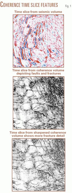
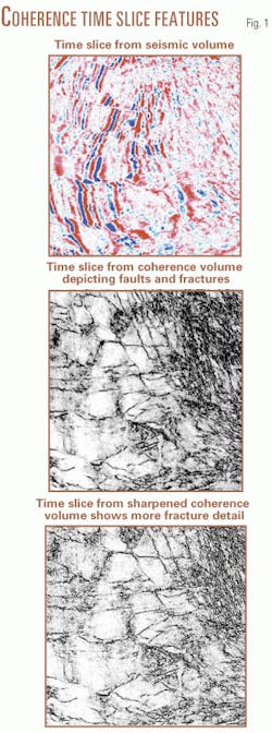
One of the most remarkable features of the coherence cube (trademark) is the accuracy with which faults and fractures can be visualized by simply looking at coherence time slices (Fig. 1). Conventional amplitudes are useful for viewing faults that run perpendicular to strike, but in complex fault zones, faults running parallel to strike become more difficult to see. The coherence cube reveals faults in any orientation, highlighting both parallel and perpendicular faulting equally well.
Sharpened coherence cubes run on restricted azimuth 3D seismic volumes offer superior imaging of fault patterns in different orientations. This technique could be of great help in deciphering subtle faults in the 3D seismic volumes and be very significant for identifying zones where productivity is influenced by fractures and faults.
Azimuth-based coherence
Interpretation of faults on vertical seismic sections can be carried out if their location and throws are discernible. Smaller faults may have a minute reflector offset and in most cases appear as an inconsequential disruption.
Similarly, minor faults are usually not directly detected but can be detected by looking for localized amplitude reduction. Thus while faults with significant throws are easily marked, small or minor faults are not so evident on the seismic data volumes, though indirect evidence (from well data or geological setting of the subsurface) does suggest the existence of faults and fractures in the area.
3D seismic surveys are usually designed to record a range of azimuths. Amongst the various reasons for looking forward to an appreciable range of azimuths, a prominent one is the desire to image small faults and locate fracture systems.
As the orientation of faults and fractures varies within a prospect, during acquisition of 3D seismic data, it is intended that these features be illuminated by some of the traveling waves. Put in another way, it may be stated as a fact: aligned vertical faults and fractures cause azimuthal variations in the seismic properties.3
However, during processing of the seismic data, "stacking" typically stacks all azimuths so that the azimuthal variation of moveout and amplitude get obliterated. It is therefore logical to expect that azimuth dependent stack would be a useful tool for seismic interpreters.
Sudhakar, et al.4 have developed a methodology that is aimed at detection of faults and fractures by examining restricted azimuth seismic volumes through the eyes of coherence.
Example from western Canada
The technique presented here was applied to a 3D seismic land data set from western Canada.
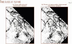
Coherence cube was run on the conventionally processed seismic volume, and Fig. 2 shows a time slice from therein at 1,524 ms, which represents the Precambrian level. Faults are seen on the slice in different orientations.
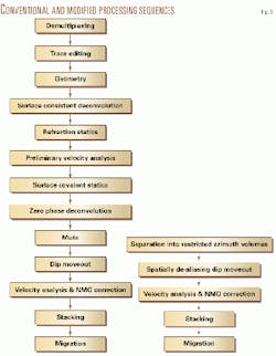
First the conventional standard processing sequence (Fig. 3) was applied to the 3D data volumes. Then, after application of surface consistent statics and zero phase deconvolution to the CDP gathers, the 3D seismic volume was binned into four different azimuth volumes according to the direction between source and receiver but within 45° of dominant fault strike. The range of azimuths fixed for each volume is 0-45°, 45-90°, 90-135°, and 135-180°.
Thereafter, processing was carried out independently for each of the four volumes. This included spatially de-aliasing dip moveout (DMO), velocity analysis, and stacking.
In the spatially de-aliasing DMO algorithm used instead of summing a DMO response to the nearest bin center, the trace is weighted and summed to the four bin centers which are the corners of the smallest rectangle containing the response trace.5 The weighting is determined by distance from the response trace to the bin center.
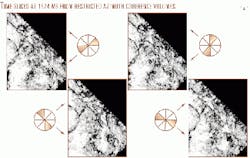
Coherence cubes were run on the different azimuth volumes using the modified eigen decomposition algorithm,6 a 5-sample eigen operator and spatial radius equal to a bin length. Fig. 4 shows a slice at 1,524 ms from each of the restricted azimuth volumes. Evidently, the accentuation of faults is different on each display and this fault detail is more pronounced than what is seen on the all azimuth slice in Fig. 2.
An important observation is that despite significantly lower fold of the restricted azimuth volumes, superior imaging is seen in the fracture-perpendicular direction. This result is intuitive to standard practices and suggests that both the fault-parallel and fault-perpendicular volumes need to be analyzed for accurate fault interpretation.
Sharpened coherence cubes
A new algorithm that combines the eigen decomposition of covariant matrices and edge enhancement operators was applied to the 3D seismic data. The output is a 3D cube of sharpened coherence coefficients. Fig. 2b depicts a sharpened coherence slice and may be compared with the corresponding coherence slice. Evidently, the fracture detail is clearer and the faults look crisper.
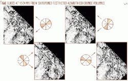
Apart from a straightforward computation of sharpened coherence cube, it is possible to impart a feeble directional bias during the sharpening process, which tends to accentuate the fault or fracture lineations. This can be done by choosing a spatial aperture in terms of the number of samples in different directions, i.e., inline, crossline, and diagonal direction or also a cube, which would include samples in all these directions. This choice can have an important bearing on the direction of faulting that needs enhancement. For example, if the faults figure in an oblique direction in the 3D volume, a diagonal spatial operator serves to show better alignment in that direction. Fig. 5 depicts the corresponding set of slices (at 1,524 ms) from the sharpened coherence volumes with directional bias. Evidently, faults can be tracked easily on such displays and their mapping could be done conveniently and accurately.
It may be noticed how much more pronounced the fault/fracture detail is. Such displays could be very important for mapping of faults. F
References
- Jones, G., Fisher, Q.J., and Knipe, R.J., eds., "Geological Society Special Publication No. 147," 1999.
- Bahorich, M., and Farmer, S., "The Coherence Cube," The Leading Edge, Vol.14, No. 10, 1995, pp. 1,053-58.
- Grimm, R.E., Lynn, H.B., Bates, C.R., Phillips, D.R., Simon, K.M., and Beckham, W.E., "Detection and analysis of naturally fractured gas reservoirs," Geophysics, Vol. 64, No. 4, 1999, pp. 1,277-92.
- Sudhakar, V., Chopra, S., Larsen, G., and Leong, H., "New methodology for detection of faults and fractures," 70th annual international meeting SEG expanded abstracts, 2000.
- Beasely, C.J., and Mobley, E., "Spatial de-aliasing of 3D DMO," 67th annual international meeting SEG expanded abstracts, 1997.
- Marfurt, K.J., Sudhakar, V., Gersztenkorn, N.A., Crawford, K.D., and Nissen, S.E., "Coherency calculations in the presence of structural dip," Geophysics, Vol. 64. No. 1, 1999, pp. 104-111.
The authors-
Satinder Chopra specializes in coherence cube processing and inversion at Scott Pickford, Calgary. He obtained his M.Phil. degree in physics from Himachal Pradesh University and joined Oil & Natural Gas Corp. Ltd. India in 1984. He has 15 years of experience in the fields of seismic processing and interpretation, specializing in depth imaging, inversion, and AVO analysis. Chopra is a member of SEG, CSEG and EAGE. E-mail: [email protected]
Vasudhaven Sudhakar is president of Scott Pickford Canada and vice-president of seismic technology for Core Lab Reservoir Management Services Division. After graduating from Madras University in 1979, Sudhakar joined GSI Singapore and managed Halliburton Geophysical's processing center from 1984 to 1990. Thereafter, he worked at the R&D department of the company before co-founding Coherence Technology Co.
