GPA research data help save time, money in BG plant design
Data from a GPA research program saved time and money in designing British Gas' Hannibal gas plant, Sfax, Tunisia.
The plant, wholly owned and operated by British Gas Tunisia Ltd., was designed and constructed by IPSI LLC/Bechtel Corp., Houston, and has been operating at full capacity since June 1996. The plant supplies more than 80% of the gas used in Tunisia.
Feed gas originates in the Miskar field, about 113 km offshore in the Mediterranean Sea. The plant is designed to produce 4.9 million cubic meters/day (MMcmd) of sales gas with less than 6.5 mole % nitrogen, a hydrocarbon dew point lower than -5° C., water content less than 80 ppmw, and a pressure of 75 barg.
The process
The feed gas from Miskar contains more than 16% nitrogen and 13% carbon dioxide. The nitrogen must be removed down to 6.5% to meet the sales-gas specification.
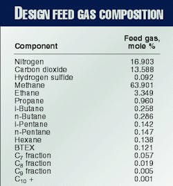
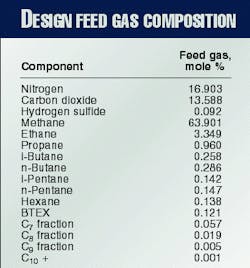
Water, BTEX (benzene, toluene, ethylbenzene, and xylene), and carbon dioxide must be reduced to low enough levels to allow cryogenic operation without solid precipitation. The design feed gas composition is shown in Table 1.
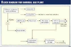
An inlet feed gas rate of 7.13 MMcmd is required to produce the 4.9 MMcmd of sales gas specified. Fig. 1 shows all the major process units in the Hannibal gas plant.
Offshore, the dehydrated gas is combined with the wet condensate and injected into a 125 km, 24-in. subsea pipeline for delivery to the plant. This two-phase feed from the Miskar field first enters the slug catcher, which consists of six 182 m, 48-in. diameter pipes. The slug catcher has a liquid capacity of 795 cu m. The gas and condensate are separated at the slug catcher.
Condensate is sent to the condensate stabilization unit. The stabilized condensate has an Rvp of 12 and is sent to storage, then shipped out by truck.
Gas from the slug catcher is first treated in the MDEA (methyl diethanolamine) unit. Carbon dioxide is removed down to 200 ppmv with 50 wt % activated MDEA solution. The acid gas from the amine strippers contains a significant amount of hydrogen sulfide, which is normally converted to sulfur in the LO-CAT unit.
After passing through the MDEA unit, the gas has very low amounts of carbon dioxide and hydrogen sulfide; however, it is saturated with water. A portion of the water is removed by the glycol unit; the remaining water is removed by the molecular-sieve unit.
The dry gas is sent to the nitrogen-rejection unit (NRU) where nitrogen is removed to produce the sales gas.
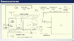
Fig. 2 shows the NRU and associated equipment.
The dry gas from the molecular-sieve dehydration unit is split into two streams. One stream is cooled by the gas-gas exchanger; the other is cooled by the gas-liquid exchanger. Two separators are used to separate the gas from the heavy hydrocarbons which condense during the cooling process.
The warm separator operates at -42° C., and the cold separator operates at -67° C. The liquid from the warm separator is flashed and warmed to 30° C. in the gas-liquid exchanger, then sent to the condensate stabilization unit.
The vapor from the warm separator is chilled and sent to the cold separator. The liquid from the cold separator combines with the liquid from the NRU as part of the sales gas. The vapor from the cold separator is cooled further to -103° C., then totally condensed and subcooled in the cold section of the gas-gas exchanger.
This condensed stream passes through a Joule-Thomson (J-T) valve and is fed to the NRU. Most of the nitrogen in the feed is distilled out in a vapor stream from the NRU. The hydrocarbon product from the NRU contains methane, carbon dioxide, and heavy hydrocarbons.
The nitrogen content in the methane product from the NRU is less than 6.5%, meeting the sales-gas specification. It is warmed to 32° C. in the gas-gas exchanger and then compressed to pipeline pressure by three stages of sales-gas compressors.
The liquid product from the NRU is pumped to 58 barg and vaporized in the reboiler to supply the reboiling duty for the NRU. It is then combined with the liquid from the cold separator and heated up to 30° C. before being fed to the suction of the second stage sales-gas compressor.
Potential freezing problems
The feed stream to the NRU is dry but still contains carbon dioxide, BTEX, and other heavy hydrocarbons. These components can precipitate in the cold section of the plant and block the passages inside the brazed aluminum exchangers.
Some of these components will be condensed and removed from the gas in the warm and cold separators to prevent them from entering the cryogenic NRU.
The coldest stream in the plant occurs during flashing of part of the cold condensate stream across a flash valve inside the NRU. Normal operating conditions at that point are -134° C. and 6.5 barg.
At these conditions, solids formation is likely. Therefore, it is very important to know the concentration of carbon dioxide, BTEX, and heavy hydrocarbons above which freezing may occur.
The GPA conducted extensive research in this area during 1998. Kurata studied the solubility of solid carbon dioxide in light hydrocarbon systems.1 Kobayashi, et al., studied the vapor-liquid equilibrium of the methane-carbon dioxide system at low temperatures down to the freezing point of carbon dioxide.2 Kohn and Juks studied the solubility of hydrocarbons in cryogenic LNG and NGL mixtures.3-5
The results of this research have helped identify the conditions at which solids precipitation will occur and hence have allowed more-accurate process design to avoid solids precipitation.
The GPA has issued a computer package based on the research results. This GPA computer program will predict the solubility of carbon dioxide, BTEX, and heavy hydrocarbons in various hydrocarbon mixtures at the most stringent conditions.
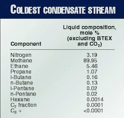
The GPA computer program was useful for designing the Hannibal gas plant because it helped predict the solubility boundary of carbon dioxide, BTEX, and heavy hydrocarbons at the coldest area in the plant. The composition of the coldest condensate stream in the plant is found in Table 2.
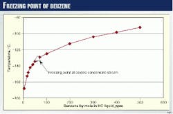
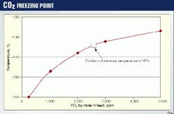
The solubility curve of benzene in the liquid is shown in Fig. 3. The solubility curve of carbon dioxide is shown in Fig. 4.
At normal operating conditions, most of the BTEX and heavy hydrocarbons will be condensed in the warm and cold separators. Therefore, the concentration of BTEX and heavy hydrocarbons in the coldest liquid is very low. If none of the BTEX is removed at the front end of the plant, the concentration of BTEX in this stream is only 13 ppm by mole.
According to the solubility curve, the freezing point is less than -150° C., well below the operating temperature of -134° C. During start-up, however, the temperature in the warm and cold separators is much warmer, and very little condensation occurs.
All the BTEX and heavy hydrocarbons will be fed to the NRU and most will be present in the condensate downstream of the flash valve. The concentration of BTEX will exceed 350 ppm by mole and the freezing point will be as high as 2105° C.
In addition, during start-up the pressure downstream of the flash valve will be much lower than the normal operating pressure (6.5 barg) in order to help cool down the plant.
Therefore, the operating temperature will certainly be lower than the freezing point during start-up. The removal of the BTEX at the front end of the plant is necessary to avoid solid precipitation during start-up.
The MDEA unit at the front end of the plant will prevent the possibility of precipitation of carbon dioxide solids in the plant. The MDEA unit will remove the carbon dioxide to a level of 200 ppm by volume. The carbon dioxide will concentrate to 310 ppm by mole in the liquid phase of the coldest stream.
Fig. 4 indicates that the freezing point at these levels of carbon dioxide is -159° C., well below the operating temperature of -l34° C.
In the event of an upset in the MDEA unit, the carbon dioxide will reach 2,700 ppm by mole (see indicated point in Fig. 4). At this level, the carbon dioxide will precipitate. The solubility curve for carbon dioxide can be used to set alarms and shutdown points at the exit of the MDEA unit.
TEG, BTEX equilibrium
The MDEA unit not only removes carbon dioxide and hydrogen sulfide but will also remove some BTEX and hydrocarbons. To avoid BTEX freezing in the cryogenic section, however, another unit is required selectively to remove most of the remaining BTEX. Triethylene glycol (TEG) solution is commonly used for dehydrating gas, but it also has an affinity for BTEX.
In this plant, the TEG unit can be used to remove both BTEX and water. The GPA has contracted DB Robinson Research Ltd. to take equilibrium data for a TEG and BTEX system.6
The collected data include TEG, water, and BETX, and cover all the conditions encountered in a TEG dehydration system.
The temperature range is from the absorber condition of 25° C. to the regenerator bottom condition of 204° C. The pressure range is from 0.4 barg to 106.5 barg.
To use these data for design, a commercial simulator was chosen. Different correlations were selected, and interaction parameters were adjusted to fit the equilibrium data.
Table 3 compares the absolute percentage deviation of concentration in the liquid phase for the different correlations: Peng Robinson, Unifac-liquid/Redlich Kwong-vapor, and Unifac-liquid/Soave Redlich Kwong-vapor. The results were all acceptable for process design purposes.
Unifac-RK was used for the original plant design because of its more accurate prediction of benzene concentration. Peng-Robinson shows a better overall fit. The interaction parameters were not adjusted to fit the data exactly since the objective was to use the data from GPA research as a guideline for the process design.
TEG simulation, plant test
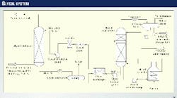
The TEG system in the Hannibal gas plant is typical (Fig. 5). It features glycol contactors, glycol regenerators, pumps, flash drum, TEG filter, glycol exchanger, and glycol cooler.
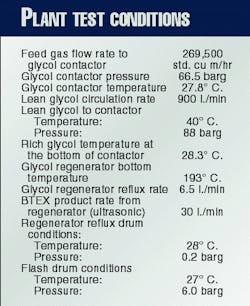
The glycol reboiler is a fired heater with glycol circulated through the coil by the reboiler pump. A plant test was recently conducted for the system using the conditions found in Table 4.
The TEG system was simulated with the Peng Robinson equation of state with the adjusted interaction parameters as described earlier and using the test conditions for flows, temperatures, and pressures.
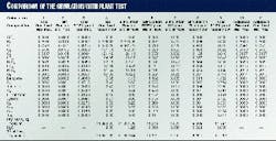
Table 5 compares the plant test and the simulation results. Columns 1 and 2 are the results of the sample analysis for feed gas and gas at the exit of the glycol contactor. The analysis of the feed gas shows that the BTEX content is very low.
The molar fractions of benzene, toluene, ethylbenzene, and xylene are, respectively, 0.0005, 0.0001, 0.0, and 0.0 in the feed gas. The molar fractions of these components at the exit of the contactor are 0.0002, 0.0001, 0.0, and 0.0001, respectively.
The benzene content is reduced from 0.0005 to 0.0002 in molar fraction. Toluene composition does not change after the gas passes through the contactor.
The analysis for ethylbenzene shows 0 for the four decimal places; therefore it must be less than 0.0001. The molar fraction of xylene is 0 in the inlet gas but shows 0.0001 molar fraction in the treated gas.
Because of its relatively high concentration, the benzene content is the only reliable analysis result for the feed and treated gas.
The chromatograph analysis reaches its sensitivity limit when the concentrations of the components fall below 0.0001 molar fraction. The analysis of the BTEX product stream from the reflux drum (Column 3) exhibits the most reliable result. The total BTEX content is more than 69%, of which benzene is 40.4%.
Unfortunately, there is no flow meter on the BTEX production line. The flow was measured with an ultrasonic method external to the flow line, so the accuracy is questionable.
The simulation using test conditions for flows, temperatures, and pressures shows good agreement with the analysis. Since the analysis of ethylbenzene and xylene concentration only shows that the concentration is less than 0.0001, the simulation feed gas was assumed to contain 0.00005 molar fraction of ethylbenzene and xylene.
The results of the simulation show that the BTEX product stream flow rate is about 11.3 kg mole/hr, equivalent to 21.4 l./min.
This flow rate is less than the 30.0 l./min from the plant test. The analysis of the BTEX product stream indicates that the benzene molar fraction is 0.404, which should be reliable at this concentration level.
The analysis of the feed gas indicates that the benzene molar fraction is 0.0005. It probably is the most reliable data in the BTEX group, since it has the highest concentration in the group. Therefore, it is more reasonable to use benzene as the key component to calculate other variables.
Column 6 of Table 5 shows the results of the simulation for the BTEX product stream. The benzene flow rate in this stream is 4.43 kg mole/hr. With this as the base, the total flow rate of BTEX can be found by dividing this value by the molar fraction obtained from the analysis.
This calculated flow rate of the BTEX product stream is 10.97 kg mole/hr, very close to the simulated value in Column 6. The rest of the BTEX components can be calculated by using the analysis results in Column 3 times the total flow rate.
Column 9 gives the calculated component flows in the BTEX product stream with the test results of concentration and the flow rate, as calculated previously. The component flows from the test are all very close to the simulation. Column 5 is the simulated component flow rate at the exit of the contactor.
Column 10 shows the simulation molar fraction of components in this stream and is very close to the analysis results in Column 2. Column 7 is the simulated gas flow from the reflux drum, and Column 8 is the simulated flash gas flow from the flash tank.
Because of the inaccuracy of the analysis of BTEX in the feed gas, the component concentrations were readjusted by adding the product streams. This adjusted composition is shown in Column 11.
The benzene composition remained the same since it is the base for the comparison. Toluene, ethylbenzene, and xylene concentrations were adjusted to 0.00021, 0.00001, and 0.0005, respectively.
As shown, the simulation using the adjusted interaction parameters agrees well with plant test results. Therefore, the water and BTEX removal predicted by the simulation can be used to design the plant.
Based on the simulation, the TEG unit can remove 80% of the benzene and more than 90% of the other BTEX components. For a lean glycol concentration of 98.7 wt %, the water content is reduced from 37.6 lb/MMscf to 5.3) lb/MMscf.
As the plant test and simulation indicate, the BTEX content in the feed is reduced by 80% in the TEG unit. This reduces the concentration of BTEX in the coldest stream to 2.8 ppm. The freezing point at this concentration is lowered to -167° C., 33° C. lower than the minimum operating temperature.
GPA benefits
The current process design for the Hannibal gas plant could not have been accomplished without the knowledge obtained from the GPA research program. The data for carbon dioxide and BTEX freezing points in hydrocarbons helped to establish the safe operating conditions for the cryogenic plant.
The vapor-liquid equilibrium data for BTEX in the TEG system helped to fix the design parameters for the TEG unit. Application of the GPA research data allowed the use of a process without the need for external refrigeration, saving 30% in capital cost compared to using an external refrigeration system.
The savings in plant capital cost was more than $35 million.
References
- Kurata, F., "Solubility of Solid Carbon Dioxide in Pure Light Hydrocarbons and Mixtures of Light Hydrocarbons," GPA Research Report RR-10, 1974.
- Kobayashi, R., Mraw, S.C., and Hwang, S.C., "The Vapor-Liquid Equilibrium of the CH4-CO2 System at Low Temperatures," GPA Research Report RR-25, 1977.
- Kohn, J.P., and Luks, K.D., "Solubility of Hydrocarbons in Cryogenic LNG and NGL Mixtures," GPA Research Report RR-22, 1976.
- Kohn, J.P., and Luks, K.D., "Solubility of Hydrocarbons in Cryogenic LNG and NGL Mixtures," GPA Research Report RR-27, 1977.
- Kohn, J.P., and Luks, K.D., "Solubility of Hydrocarbons in Cryogenic LNG and NGL Mixtures," GPA Research Report RR-33, 1978.
- Ng, H.J., Chen, C.J., and Robinson, D.B., "The solubility of Selected Aromatic Hydrocarbons in Triethylene Glycol," GPA Research Report RR-131, 1991.
The Authors
Steve Jones is currently project manager for the BG International Miskar Expansion project. He was project manager for the Miskar Enhancement project and commissioning manager for the Miskar project.
Jones' previous experience includes major projects and operational roles for both British Gas and Aramco in the UK, United States, Holland, and the Middle East. He holds an MS degree from the University of Lancashire, England.
Sarah Lee is currently the senior production engineer for the British Gas Miskar Asset project and was previously a project engineer on both the Miskar enhancement and expansion projects. Lee graduated from the University of Cambridge, England, with a BS in chemical engineering, after which she was a BG graduate and involved in numerous research positions.
Roger Chen is a senior vice-president of IPSI LLC, a unit of Bechtel Corp. He has more than 25 years' experience in research, process design, and development in the areas of gas processing and oil and gas production.
Chen has authored five patents, with several pending, and is the author of more than 30 technical publications. He holds a BS degree from National Taiwan University and MS and PhD degrees from Rice University, all in chemical engineering. He is a member of AIChE, ACS, and the Gas Processors Association Research Steering Committee.
Megan Evans is a process engineer with IPSI LLC, a division of Bechtel Corp. in Houston. She has 5 years' experience working on gas processing and LNG projects, including the Atlantic LNG plant in Trinidad. Evans holds a BS in chemical engineering from Rice University.
