Models support potential for drilling deep microholes
Microboreholes-Conclusion
Analysis of developed models suggests that no fundamental or theoretical reason exists to prevent relatively deep microholes from being drilled with hydraulic motors deployed on a coiled-tubing drillstem.
The models do not rule out high performance drilling at greatly reduced cost in many areas and, under some assumptions, actually support this premise, even in deep wells.
Field testing of prototype microdrilling systems is needed to test and refine some of the predictions the simple models foretell.
The potential size of borehole instrumentation using state-of-the-art electronics and sensors makes microholes ideally suited for such nonproducing holes as exploration, reservoir characterization, and well monitoring.
Part 1 of this two-part series (OGJ, Jan. 10, 2000, p. 39) presented the concept of drilling deep microboreholes (1 to 2-in. diameter at total depth) for exploration and longer-term reservoir monitoring. This concluding article examines the theoretical limits on microdrilling and the feasibility of developing a high-performance microdrilling system based on coiled tubing.
Microdrilling concept
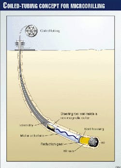
Fig. 1 shows the microdrilling system: a mechanical rotary drag bit, an hydraulically powered positive-displacement motor (PDM), and a coiled-tubing drillstem.
While it is assumed that underbalanced drilling and directional drilling will be essential elements of a microdrilling system, only conventional incompressible drilling fluids and vertical drilling are considered in this initial examination. The system is a miniaturization of conventional coiled-tubing drilling technology that will meet both requirements.
Basis of selection
Coiled-tubing drilling was selected to provide a simple surface platform that readily supports highly automated and remotely controlled drilling. Coiled-tubing supports straight-hole and directional drilling and provides low-cost, hard-wired telemetry for measurement-while-drilling (MWD), log-while-drilling (LWD), and downhole process control.
Coiled tubing also provides high-integrity wellhead pressure-control that is required for deep holes, exploration holes, and under-balanced drilling, and for drilling and formation testing of through-tubing drilled micro-laterals in petroleum reservoirs.
Drag bit performance is readily described with published models1-4 and the polycrystalline diamond compact (PDC) bit concept is well suited for miniaturization. Hydraulic-powered, downhole PDMs are essential for most directional drilling systems. They have been used routinely for both straight and directional coiled-tubing drilling.
Miniaturization of PDM motors is theoretically feasible; fabrication issues are the major technical challenge. Commercial coiled tubing is currently available in the sizes required, but three improvements will be needed for deep commercial microdrilling: removal of the internal weld bead (in very small diameter tubing), increased wall thickness, and higher-strength tubing.
Cuttings transport performance and friction loss for conventional drilling fluids are readily characterized with published fluid models for incompressible fluids.
Theoretical feasibility
Evaluating the microhole concept involved identifying major components of the proposed drilling system and predicting their performance in terms of the drilled diameter using simple models from published papers.
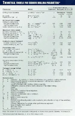
The ratio of the slender (microbore) diameter to a nominal deephole diameter (8 ¾ in.) is defined as the dimensionless diameter, D. The coiled-tubing drilling system's theoretical performance was evaluated in terms of D to determine the effect of well diameter on drilling-system performance. The box on this page summarizes the results discussed presently.
Assumptions
Therefore, bit-wear flat-area is assumed proportional to D during the useful life of the bit.
- Critical buckling load for the coiled-tubing drillstem is predicted by Dawson and Paslay's inclined straight hole buckling model or a simplification of Qiu and Miska's or Wu and Juvkam-Wold's buckling models for high-curvature holes.5-7
- A beam-resonance model predicts the lowest resonant frequency of the BHA.
- A low-viscosity, incompressible, Newtonian, drilling fluid conveys power from the surface for power conversion in the PDM and for annular cuttings transport.
- The annular flow velocity is bracketed by a conservative rule-of-thumb value for minimum annular velocity on the high side and the Stokes terminal-settling velocity for a maximum particle size that scales with the well diameter on the low side.
- Specific energy is defined as the energy per unit volume of rock drilled. It is a process-dependent property that is expected to vary with changes in rock, bit, and fluid type, bit speed and weight, depth, and local rock stresses.
It is assumed that the specific energy for drilling is bracketed by a specific-energy value that is unchanged as D is reduced (specific energy being a property of the rock) and a specific-energy value that varies as the cube of the inverse of particle diameter and is a property of the surface created and proportional to D3.
Model development
Published algorithms for drag-bit performance produce a simple model of the mechanical drilling process.2 The penetration rate for rotary bits is the product of the rotary speed and the depth of cut per bit revolution.
Depth of cut is a function of the axial bit thrust. Increasing the rotary speed or the bit thrust increases the drilling rate.
Localized overheating of the PDC cutter surfaces, high-cutter loads, and impact are the main cause of excessive wear and premature failure. Therefore, cutter temperature and impulse loads limit penetration rate.
Maximum bit thrust may be limited by either the allowable cutter temperature (assumes rotary speed held constant) or by the ability of the drilling system or BHA to develop or transmit axial force to the bit.
Force transmitted through the drillstem and the drilling assembly generates bit thrust within the BHA. Tractors or bit thrusters that generate thrust within the BHA are not considered.8
Buckling of the drillstem under compression loading precedes friction lock-up that caps the maximum transmitted force. The initiation of buckling produces a conservative value for the maximum bit thrust based on force transmission.
As the lowest natural frequency of the BHA is approached, bit motion becomes unstable with the vibration becoming potentially destructive. In a conservatively operated system, the lowest natural frequency of the rotating BHA determines the maximum rotary speed.
Power transport from the surface to the bit may also limit penetration rate. The power needed at the bit is estimated with the drilling specific-energy. Determining accurate, specific-energy values requires downhole testing; it is assumed that real drilling processes lie within the assumed extremes defined previously.
Performance predictions
The box lists the various simple models developed to analyze the effect of D on drilling performance. The resulting D exponent formula and the predicted performance response are shown as multipliers for Berea Sandstone and Sierra White Granite for a case in which D = 1/5.
Depth-of-cut
The bit thrust and formation determine depth of cut. Glowka has shown2 that the depth-of-cut is a function of the cutter-penetrating stress raised to an exponent value n. Measured values of n were 0.42 for Sierra White Granite and 0.65 for Berea Sandstone.
The depth-of-cut is proportional to the quotient, bit thrust divided by D, raised to the 1/n power, where 1/n is less than 1.0. If bit thrust is maintained at a constant value while D is reduced from 1.0 to 1/5, the depth-of-cut is increased by a factor of 12 for Berea Sandstone and by 46 for Sierra White Granite.This result is academic where bit thrust is limited by drillstem buckling but it does indicate the promise of downhole thrust generation where bit materials support drilling at very high-cutter-loads.
This result emphasizes the importance of operating at the maximum bit weight, as opposed to operating at the maximum rotary speed.
Bit thrust
The compressive force at the onset of drillstem buckling limits maximum transmitted bit thrust. The bit thrust at frictional lock-up between the drillstem and the bore is somewhat greater than the force at the onset of buckling.
Published drillstem buckling models for various well-trajectory scenarios have been modified to evaluate the effect of D on the critical buckling load. The modified Dawson and Paslay model5 predicts that the onset of bulking in an inclined straight hole scales as D5/2.
The modified Wu and Juvkam-Wold or Qiu and Miska models6 7 predict that the onset of bulking in a high-curvature hole scales as D3. A factor of 5 reduction in bore size, therefore, reduces the maximum transmitted bit thrust by a factor of 55 for a straight hole and 125 for a high-curvature hole.
Rotary speed
The onset of severe bit vibration or excessive temperature of the cutter surfaces limits maximum rotary speed. Published drag-bit drilling models are not readily adapted to predicting steady-state cutter vibrations or impulse loads as a function of bit speed.9
A recently published model proposes a method to determine the onset of severe BHA vibration for conventional rotary drilling, but the approach will require considerable adaptation to be used to evaluate coiled-tubing drilling.10
In the absence of a more comprehensive model, a bending-mode resonance model for beams was applied. With the axial length of the (rotating) BHA held constant, the bending-mode natural frequency scales as D.
A factor of 5 reduction in bore diameter decreases the maximum rotary speed by a factor of 5 for a stationary drillstem and an unchanged rotating BHA length.
With the BHA length reduced by the fraction D, natural frequency scales as D-1. A factor of 5 reduction in bore diameter increases the maximum rotary speed by a factor of 5 for a stationary drillstem and the shortened BHA.
Cutter temperature
Cutter temperature may also limit the maximum rotary speed. The friction between the moving bit cutters and the rock generates heat in both the cutter and the rock.
Glowka and Ortega have developed thermal transport models that predict the maximum bit thrust as a function of cutter velocity.3 4 Glowka's model was simplified to include only a high-cutter-speed, thermal-transport regime.
This simplified model predicts a critical bit thrust that is proportional to the square root of the quotient of the bit diameter divided by the rotary speed.
Setting the drillstem's critical buckling force equal to the temperature-limited bit thrust and solving for rotary speed determines the maximum rotary speed.
For a straight, inclined hole, the calculated maximum rotary speed is proportional to D-4; for a high-curvature hole, the calculated maximum rotary speed is proportional to D-5. A factor of 5 reduction in bore diameter increases the maximum bit speed by a factor of 625 in a straight-hole and 3,125 in a high-curvature hole.
Hydraulic power
Available power to the bit can also limit drilling performance. The internal-pressure rating of the coiled tubing and the maximum flow rate determine the maximum hydraulic power that can be supplied to the downhole system.
Assuming that diameter-to-thickness ratio of the coiled tubing is held constant as D is reduced, the maximum allowable internal pressure is proportional to the diameter-to-thickness ratio and is unchanged with the reduction of D.
The maximum flow rate is limited by the frictional pressure loss in the tubing and the annulus. The differential pressure available to produce the flow rate is the pressure remaining after the pressure drop in the motor and the pressure drop required for cuttings transport in the annulus are subtracted from the allowable internal pressure.
A numerical Newtonian flow model shows that hydraulic power transport scales as D5/2 for a constant annular-velocity model. The constant-velocity model predicts a reduced power per unit hole area as the bore diameter is reduced.
The same numerical Newtonian flow model shows that hydraulic power transport scales as D2 for a Stokes terminal settling-velocity model. This model assumes that the tubing wall and internal working pressure are increased slightly as D is reduced so that the input hydraulic power per unit area is unchanged with respect to D.
This is a small violation of the first model assumption, described earlier, and requires that the diameter-to-thickness ratio of the tubing increase gradually as D is reduced to compensate for increasing flow friction losses.
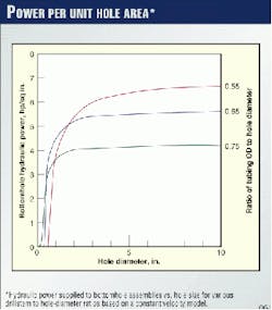
This settling-velocity model predicts a constant power per unit hole area as the bore diameter is reduced until the friction drop becomes excessive (Fig. 2).
The power output of an ideal PDM is the product of the volumetric flow through the motor, the volumetric efficiency, the pressure drop across the motor, and the mechanical efficiency.11
Assuming that the two efficiency factors and the maximum allowable pressure drop across the motor are relatively constant with variation of D, the maximum circulation flow scales as the bore area, D2. The power output density (power per unit bore area) should be constant relative to D.
Dynamometer testing of commercial motors as small as 1½ in. supports the prediction. Fabrication of the stators for the motors may pose a major challenge in the downsizing of motors, but no theoretical limits on the performance of micro-motors are anticipated.
Penetration rate
The maximum penetration rate model assumes the following:
- Penetration rate varies linearly with both depth-of-cut and rotary speed.
- Depth-of-cut is determined from the bit thrust using Glowka's non-linear drilling model.2
- Buckling of the drillstem limits the maximum bit thrust that can be transmitted to the bit.
- Maximum rotary speed is the lesser of the resonant-frequency-limited speed or the cutter-temperature-limited speed at the maximum bit thrust.
- Maximum penetration rate will be achieved with a bit thrust equal to the critical buckling load of the drillstem and the maximum rotary speed.
The critical buckling load decreases dramatically as the drill-stem diameter is reduced. The resonance-limited maximum rotary speed increases as the rotary drilling assembly diameter or the assembly length is reduced.
The maximum rotary speed, at critical buckling load bit thrust, increases dramatically as the diameter is reduced when cutter temperature limits the maximum speed.
The net effect of decreasing the bore diameter on penetration rate is developed presently for the most applicable sets of assumptions and summarized in the box for all of the cases investigated.
BHA-limited penetration rate
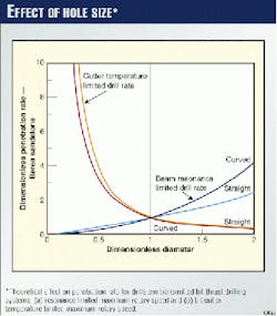
If the bit thrust is limited to critical loads from the buckling models and the speed is limited to the lowest natural frequency of the drilling assembly, the penetration rate decreases significantly with the reduction of well diameter. In this case, the penetration rate scales as D(3/2*-n)/n in a straight inclined bore and D(2-n)/n in a high-curvature bore.In Berea Sandstone, a factor of 5 reduction in bore size reduces the maximum penetration rate by a factor of 8 for a straight hole and 28 for a high-curvature hole. In Sierra White Granite, the same reduction in bore size reduces the maximum penetration rate by a factor of 63 for a straight hole and 426 for a high-curvature hole (Fig. 3).
If the bit thrust is limited to critical loads from the buckling models and the speed is instead limited by the bit cutter temperature at the buckling load, the penetration rate is significantly increased with the reduction of well diameter.
In this case, the penetration rate scales as D3/(2*n)-4 in a straight inclined bore and scales as D2/n-5 in a high-curvature bore. In Berea Sandstone, a factor of 5 reduction in bore size increases the maximum penetration rate by a factor of 15 for a straight hole and 22 for a high-curvature hole.In Sierra White Granite the same reduction in bore size increases the maximum penetration rate by a factor of 2 for a straight hole and 1.5 for a high-curvature hole (Fig. 3).
Penetration rate
Two scenarios are proposed that should bracket reality.
1. Hydraulic-power-transport density is assumed be independent of D. If the bit power is limited to the hydraulic transport power, the penetration rate is reduced or unchanged with the reduction of well diameter, depending on the velocity model that is assumed.
The penetration rate scales as D1/2 for the constant velocity model and as D0 for the Stokes law terminal-velocity model. A factor of 5 reduction in bore size decreases the maximum penetration rate by a factor of 2 for the constant velocity model.
The maximum penetration is unchanged for the Stokes law, terminal velocity model.
2. The annular clearance and therefore the particle diameter are required to scale as D. Then it is reasonable to assume that the specific energy scales as D-3.
Where the bit power is limited to the hydraulic transport power, the penetration rate is reduced or unchanged with the reduction of well diameter, depending on the velocity model that is assumed.
The penetration rate scales as D7/2 for the constant velocity model and as D3 for the Stokes law terminal-velocity model. A factor of 5 reduction in bore size decreases the maximum penetration rate by a factor of 280 for the constant velocity model and by a factor of 1/125 for the Stokes law terminal-velocity model.
Bit performance
Recent testing of bottom-hole assemblies for drilling 1.75-in. and 2.32-in. holes suggests that penetration rates for microhole drilling may match or exceed common rates for shallow production hole drilling.
Table 1 of Dreesen and Cohen presents encouraging test results for small drill bits under a variety of conditions.12
Necessary elements
The foregoing results show that reducing hole size by simply reducing the scale of drilling components will reduce drilling performance. For currently acceptable nominal drilling performance to be achieved, a microdrilling system will be required that includes the following essential elements:
- A nonrotating, coiled-tubing drillstem to avoid the low natural frequency of a long unsupported rotating drillstem.
- An extremely short rotating bottom-hole drilling assembly. With the unsupported sections of the rotating elements sufficiently short, the resonance-limited maximum rotary speed can be increased to approach the maximum speed allowed by the bit cutter temperature.
Conventional design practices for downhole drilling motors need to be adapted to produce shorter, dynamically balanced, rotating drilling assemblies that operate at significantly higher speeds than normal for larger motors. The bit will have to be adapted to support these higher speeds.
- The tubing-OD to bore-diameter can be increased from a typical value of one half for nominal drilling to two thirds or possibly three fourths. Increased buckling loads will be achieved for both the inclined straight-hole model and the high-curvature model.
Numerical models of Newtonian and power law fluids show that transport of hydraulic power will be increased with an increase in the tubing-OD to bore-diameter to about two thirds (Fig. 2).
- The tubing OD/ID ratio can be decreased to provide a higher internal working pressure for the coiled-tubing. The annular velocity can be reduced by engineering fluids to produce an optimal rheology, reducing the friction losses and increasing hydraulic-power transport.
- Antiwhorl, mechanically balanced, PDC bits that support high-rotary-speed, low depth-of-cut, and low-amplitude bit vibrations. Reduced bit thrust and increased rotary speeds will naturally produce smaller particle sizes.
In order to pass through the reduced annular clearances without plugging, small particles will have to be produced at the bit. These cuttings will be removed at significantly lower annular fluid velocities than required for nominal particle sizes.
For microdrilling rates to compare well with or exceed conventional-sized-hole drilling performance, micro bits will need to operate at similar or lower specific energies than attained in standard-bore drilling. Developing a low specific-energy microdrilling process appears to be the highest-risk element of the microdrilling concept.
A review of laboratory and downhole specific-energy data shows that rotary mechanical and percussion drilling produce the most efficient drilling processes with all other processes tending to require more than an order-of-magnitude higher power.
Much of the data come from small-diameter, shallow, mining blast holes and laboratory-scale drilling tests. For now, it is assumed that rotary-percussion processes will also be the most efficient for deep-hole microdrilling.
Improved drilling efficiencies using bits designed for combined rotary percussion drilling, underbalanced drilling, kerfing, or high pressure jet processes may be needed to achieve the specific energy values required for commercial drilling performance.
If the bending resonance of the BHA is the major contributor to the overloading of bit cutters, then rotating BHA components can be designed to be shorter, stiffer, and less massive to increase their lowest natural frequency.
Where bit thrust is transmitted through the drillstem and not developed with a massive, rotating drill-collar assembly, it is feasible to make the rotating assembly very short and stiff. Increasing drillstem diameter relative to the bit diameter as bit size is reduced can increase the stiffness of the drillstem.
Cuttings; filter cake
Assuming that bits can be designed to produce cuttings small enough to fit in the reduced-clearance annuli, cuttings transport presents no fundamental restriction on minimum hole size.
Simultaneous optimization of both cuttings transport and hydraulic-power transport will be complicated but feasible using modern drilling simulation software.
Traditional drilling fluids and drill-cutting formation processes develop filter cake of 1/16 to 3/16-in. thick over porous zones. While filter cake reduces hole diameter, it seldom poses a serious restriction in normal holes sizes.
In microholes, such filter cake represents a 6-18% reduction in diameter and a 12-34% reduction in flow area. With the large reduction in flow area, filter cake may be abraded by normal annular flow with the result that excessive fluid loss to porous formations occurs.
The forces that form and maintain the filter cake are not believed to be diminished with hole size. The restrictions therefore can stick drilling assemblies during trips. This may represent a major technical challenge for microdrilling.
The use of underbalanced drilling or specialty drilling fluid systems specifically designed to develop very thin filter cake is suggested. The potential increased cost of specialty drilling fluids should be more than offset by the greatly reduced volume of fluid needed.
Underbalanced drilling seems to be highly compatible, at least in shallow holes, with the proposed coiled-tubing system. Where it can be applied, it should eliminate problems with filter cake formation.
Greatly reduced particle-size distributions are a prerequisite for microdrilling and smaller cuttings intuitively should reduce the cake thickness required to control fluid loss.
Industry issues
Miniaturized drilling does not appear to add any challenges not already encountered in conventional drilling at the larger sizes.
Pressure control is often mentioned in the context of the reaction time. These arguments are only justified in the context of microhole drilling from a conventional drilling platform as opposed to a system properly scaled for microhole drilling.
Perhaps, counter-intuitively, the magnitude and lag-time for a pressure pulse to arrive at the surface does not change with well diameter, and sensitivity of pit level alarms is readily increased by reducing the surface area of trip tanks and pits.
Other potential problems raised as major disincentives for microdrilling involve hole spudding and setting of conductors, and surface and intermediate casing. It is conceivable that a microdrilling platform could be configured to drill and install both microconductor and reeled surface and intermediate casings. Conductors and surface casing are frequently set with small specialty rigs for conventional sized holes.
Similar techniques to spud microholes will evolve where economics require it.
Issues such as directional drilling, well completion, fishing, logging, and ultimately well plugging are all raised as possible obstacles. Each will have to be addressed in turn, but none appears to present a fundamental impediment to the microdrilling concept when a mature technology exists.
Acknowledgments
The authors acknowledge the discussions of microhole drilling with Michael Gelfgat, Aquatic Co., Moscow; John Cohen, Maurer Engineering Inc., Houston; and Scott Quigley, Coiled Tubing Engineering Services, Houston. Jim Thomson, Lithos Associates, Las Vegas, provided a comparative analysis of microhole drilling in relation to holes of conventional diameter.
References
- Dotournay, E., and Defournay, P., "A Phenomenological Model for the Drilling Action of Drag Bits," Int. J. Rock Mech., Min. Sci. & Geomech. Abstr., Vol. 29, pp. 13-23, 1992.
- Glowka, D.A., "Use of Single-Cutter Data in the Analysis of PDC Bit Designs: Part 1-Development of a PDC Cutting Force Model," JPT, August 1989.
- Glowka, D.A., and Stone, C.M., "Thermal Response of Frictional Heating and Convective Cooling of Polycrystalline Diamond Drag Compact Cutters Under Simulated Downhole Conditions," SPE Journal, April 1985.
- Ortega, A., and Glowka, D., "Frictional Heating and Convective Cooling of Polycrystalline Diamond Drag Tools During Rock Cutting," SPE Journal, April 1984.
- Dawson, R., and Paslay, P., "Drillpipe Buckling in Inclined Holes," JPT, October 1984.
- Qiu, W., and Miska, S., "Effect of Coiled Tubing Initial Configuration on Buckling Behavior in a Hole of Constant Curvature," 1998 SPE/IcoTA Coiled Tubing Roundtable, Houston, Apr. 15-16, 1998.
- Wu, J., and Juvkam-Wold, H.C., "Coiled Tubing Buckling Implication in Drilling and Completing Horizontal Wells," SPE Drilling & Completions, pp. 16-21, March 1995.
- Leising, L.J., Onyia, E.C., Townsend, S.C., Paslay, P.R., and Stein, D.A., "Extending the Reach of Coiled Tubing Drilling (Thrusters, Equalizers, and Tractors)," SPE/IADC Drilling Conference, Amsterdam, Mar. 4-6, 1997.
- Guo, B. and Geir, H., "Bit Wobble: A Kinetic Interpretation of PDC Bit Failure," SPE/ATCE, New Orleans, September 1994.
- Abbassian, F., and Dunayevsky, V.A., "Application of Stability Approach to Torsional and Lateral Bit Dynamics," SPE Drilling & Completions, June 1998.
- Samuel, G.R., and Miska, S., "Analytical Study and Performance of Positive Displacement Motor (PDM) Modeling for Incompressible Fluids," 5th Latin America and Caribbean Petroleum Conference and Exhibition, Rio de Janeiro, Aug. 30-Sept. 3, 1997.
- Dreesen, D.S., and Cohen, J.H., "Investigation of the Feasibility of Deep Microborehole Drilling," Los Alamos National Labortory Report, LA-UR-96-4631; proceedings of the 8th Annual Energy Week Conference and Exhibition, Houston, Jan. 28-30, 1997.
