TOP-OF-LINE CORROSION-Conclusion: Models updated; remediation strategies set out
Part I of this two-part series (OGJ, July 10, 2000, p. 58) demonstrated that top-of-line corrosion (TLC) in wet-gas pipelines correlates with water-condensation rate (WCR). A model was developed to calculate WCR along the pipe profile and to evaluate the risk of TLC.
This conclusion indicates how corrosion-prediction models can be updated and presents remedial actions for the prevention of TLC.
Calculations
In-house corrosion model Lipucor,1 normally dedicated to bottom-of-line corrosion prediction, was been updated for TLC evaluation, with the following assumptions and adjustments:
- The pipe is full of gas. The WCR, used as an input, is calculated by the line-simulation package.
- The water condenses at the top of the pipe wall and slowly drops down to the bottom of the pipeline without being noticeably affected by the gas flowing by. The raw corrosion rate calculated by Lipucor that accounts for the flowing velocity of the gas phase is therefore corrected.
- The water wetting is 100%.
- The condensation factor published by De Waard, et al.,2 was integrated in the program to correlate the WCR-to-TLC rate.
The results given by Lipucor lead to TLC rates of 1 to 2.5 mm/year in field cases cited in Part 1, which are quite close to the actual corrosion rates. In its present status, Lipucor does not account for the following facts in the corrosion-rate calculations:
- Solubility of the CO2 in the condensed water at top of the line, much lower than the one in the produced water at the bottom of the line. (In case of heavy external cooling, the internal skin temperature at top of the line is lower than the bulk effluent and bottom-water temperature.)
- Difference in the iron carbonate solubility (and consequently, in the possible formation of a protective scale) between the top and the bottom of the line.
- Impact of the saturation of the condensed water by iron carbonate. Nevertheless, the interpretation of the field data clearly indicates that such saturation is only possible if the condensation rate is less than 0.25 ml/(sq m.sec). As long as localized corrosion occurs, it is difficult to talk about a protective film by saturation effect.
- The influence of organic acids. The bottom-line water temperature being higher than the top-of-line water, the organic-acid content of the latter is much higher than that of the former.
In the absence of corrosion inhibitor and very high concentration of organic acids, the formation of a protective film is unlikely. This is the cause of high TLC rates observed in some of the gas lines.
Actions
Different possibilities were evaluated for preventing and controlling TLC. If the TLC risk is predicted during the design, the operating company has the choice to invest in one of the following options:
- Clad pipe.
- Batch treatment with permanent pigging facilities.
- Pipe burial with sufficient burial depth or heat insulation for the whole pipe length to prevent water condensation.
- Water drop-out upstream of the pipe inlet.
If TLC is detected by inspection in an operating line, control can only be accomplished by batch treatment or water drop-out upstream of the pipe inlet (process modification).
- Batch treatment. For successful treatment, careful selection of an oil soluble-corrosion inhibitor and determination of the batch-treatment frequency and contact time between inhibitor solution and pipe surface are necessary and require a specific laboratory study.
The batch of inhibited solution (typical dilution rate of 10% volume), trapped between two pigs, ensures a contact of the corrosion inhibitor with the top of the line and the creation of a corrosion inhibitor film. Precautions should be taken to avoid the presence of a gas pocket at top of batch of liquid, as it may prevent filming on the pipe surface.
The length of the batch should be sufficient to allow a contact time of 3 to 10 sec (depending on corrosion inhibitor and solvent used for dilution) between inhibited solution and pipe surface. A monthly batch treatment is minimal.
The main drawback of batch treatment is its consequences for water-treatment units, as most corrosion inhibitors have a strong tendency to form emulsions. The chemical supplier should be involved in inhibitor selection to find the right formulation to minimize oil in water.
The problem of oily water can be solved by injection into a disposal well. Another drawback of batch treatment is reduction of the production rate to achieve a proper batching at reduced flow rate.
- Cladding the line. The pipeline section with potential TLC risk (the predicted WCR is greater than the threshold) can be internally clad with AISI 316L or Alloy 825.
Determination of pipe length to be clad can be made by specific analysis that uses the methodology previously mentioned.
It does not induce any process modifications upstream or downstream, which is the main advantage of this solution. The main drawback is the cost of the clad pipes: about eight to 12 times that of the standard carbon steel pipe.
- Thermal insulation. This solution allows maintenance of the WCR at less than a defined threshold.
Different systems, using polypropylene (PP) or ethylene-propylene-diene-monomer (EPDM) or a combination of 4-mm neoprene covered by 19 mm solid polyurethane, were evaluated in Line B conditions.
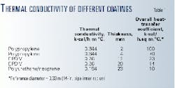
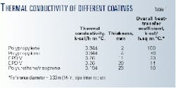
Table 1 gives the thermal conductivity of these systems; U0 values for 2 mm thick PP are five times higher than the one for EPDM. The results can be summarized as below:
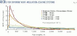
A 2-4 mm thick polypropylene coating does not seem to be sufficient. The condensation rate decreases with the increase of PP thickness, but about 500 m more pipe will be corroded as a longer pipe section is subject to a WCR greater than 0.25 ml/(sq m.sec) (Fig. 1).
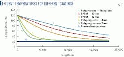
The pipe temperature reaches the external temperature within 6 km for 2 mm of PP and 8.3 km for 4 mm of PP. With 12 mm of EPDM, the temperature decreases more slowly and reaches the external temperature after 26 km.
For 20 mm of EPDM, the outlet temperature is 33 degrees C., which is much higher than the external temperature. For the PE-neoprene configuration, the temperature decrease is linear; the outlet temperature is 45 degrees C. (Fig. 2).
It is preferable, therefore, to select a low-thermal-conductivity coating instead of increasing the thickness of a highly conductive coating. The heat insulation should be applied on the entire length of the pipe or at least on the unburied section, such as a dogleg.
The heat insulation of field joints should be studied very carefully. Moreover, this option may lead to an increase of the effluent temperature at the outlet of the line that must be compatible with design conditions of the downstream process.
- Line burial. The field experience showed that the burial of the line can be considered as excellent heat insulation,3 to be evaluated case by case.
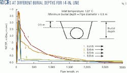
The efficiency of pipe burial for prevention of TLC is investigated for a 14-in. line and for burial depths of 1 m, 0.8 m, 0.5 m, 0.4 m, and 0.2 m (Fig. 3). The riser coating is 12-mm EPDM, and the external anticorrosion coating is 2-mm polypropylene.
For depths of 0.2, 0.4, and 0.5 m, the WCR is greater than 0.15 ml/(sq m.sec), which is the critical WCR for this application, with respective lengths of pipe subject to TLC of 1.8 km, 2.4 km, and 3 km.
If the line is incompletely buried, the length of corroding pipe section increases with the increase of the burial depth. The minimum burial depth required to ensure adequate heat preservation and subsequent TLC prevention is, in this 14-in. line case, around 0.8 m-more than twice the pipe diameter.
Only a "complete burial" depth can be considered efficient heat preservation; that is, with a burial depth of 0.5 m in this case, the effluent temperature remains greater than the external temperature.
For a 0.2-m "partial burial," the temperature profile is the same as for an unburied pipe coated with 2 mm of polypropylene, and the effluent temperature reaches the ambient temperature after only 7 km.
- Water drop-out. In order to limit the WCR in the line below the critical threshold for TLC, the effluent can be cooled upstream of the line inlet. This solution, however, requires bulky equipment on remote platforms.
Addressing the risk
TLC is a major risk for hot wet-gas lines and should be considered during the design phase. The accuracy of WCR prediction may have significant impact on the project cost because some TLC control options are significantly expensive even if, in all field cases, TLC is restricted to the first 1-3 km of the lines.
The prediction requires integrated and validated models including thermodynamic, hydrodynamic, thermal exchange, and line-simulation packages.
If TLC is detected in a line already in operation, the main cost is the production loss during batch treatments because it is necessary to reduce the production rate. The design, manufacture, and installation of pigging facilities (if not installed during pipe construction) require time; it is almost impossible to protect the line during this period.
TLC is restricted to the lines whose flow regime is stratified wavy or stratified smooth. Annular flow regime may be encountered in risers for offshore lines where no TLC has been encountered.
Slug flow may occur at specific locations (uphill sections) for very low flow rates. Operators will intermittently wet the top of the line with a bulk liquid containing some corrosion inhibitor and thereby ensure some sort of "natural" batching.
Unfortunately, most of the wet-gas lines are designed for operating in stratified flow or will be operated in that mode with production decline. TLC prediction should be done considering the production profile for the field life.
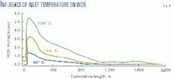
High inlet temperature of the effluent dramatically increases the WCR especially for inlet temperature in the range of 60 degrees C. to more than 120 degrees C. (Fig. 4).
Reducing the temperature upstream of the line requires more space on the platforms and greater investment. Gas cooling may be impossible on the wellhead platforms. In any case, temperature reduction is a costly operation.
The WCR is also directly correlated to the gas flow rate because the condensing water comes from the gradual cooling of the hot saturated gas phase along the sections of lines exposed to high cooling rate.
Obviously, the higher the gas flow rate, the larger the amount of saturation water at inlet conditions ready to drop out further downstream in the line. The flow regime depends mostly on the gas velocity and on the line profile.
There are no physical means to modify the flow regime to drop the WCR below a "safe" threshold, unless the gas flow is reduced to a very low level incompatible with the production planning and proper operation of the line.
Ho-Chung-Qui reported that in all gas fields operated by his company, where the H2S/CO2 ratio was greater than 1/1, no TLC was reported.4
This can be explained by the fact that the solubility of iron sulfides is very low compared to that of iron carbonate. Therefore, complete dissolution of the iron sulfide is only possible by higher dilution rates by condensing water.
Finally, in all cases, with or without H2S, the competition between the condensation rate and the saturation of the condensed water in iron will govern the TLC rate. That is why it is unlikely that there is a universal critical WCR value above which the TLC takes place.
The risk evaluation should take into account not only WCR but also the pH of the condensed water in the actual conditions and the organic acids contents of the condensed water.
The most important organic acid is acetic acid whose presence increases the risk of localized TLC. Analysis of the produced water is essential for TLC risk evaluation.
Complete burial of the pipe seems to be the most appropriate solution for TLC prevention, provided that tight installation (trenching and back-filling) procedures are followed to ensure more than 1D thickness (or at least 0.5 m) of the soil layer above the top of the pipe and to avoid upheaval buckling.
Its advantage over heat insulation is the absence of risks of insulating coating damage, of coating ageing at high temperatures, and, over time, of field-joint coating damage on barges. The drawback is that the gas-outlet temperature will be high.
Even though its cost is somewhat high, the cladding of the first few kilometers of pipe can be envisioned if the pipe burial is difficult, or very costly, or if there is a risk of back-filling removal by the water currents (mainly offshore lines).
Inspection by intelligent pigging showed no bottom-line corrosion, which indicates that corrosion inhibition by continuous injection is effective. The corrosion inhibitor, however, being condensate-dispersible and water-soluble, drops rapidly in the stratified liquid bulk and is therefore ineffective to mitigate TLC.
For the lines in operation and affected by TLC, there is no other way than batch treatment using an oil soluble product.
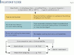
Existing corrosion-prediction models can be easily updated for the prediction of TLC rate. The different aspects of the evaluation of the TLC risk are shown on Fig. 5.
Acknowledgment
The authors thank Totalfina for permission to publish this series and C. Goulay, P. Duchet-Suchaux, F. Jacob, and D. Vinazza, Totalfina Exploration Production, for their contribution in modeling and validation work.
References
- Gunaltun, Y.M., "Combining research and field data for corrosion rate prediction" Corrosion/96, Mar. 24-29, 1996, Denver.
- de Waard, C., Lotz, U., and Milliams, D.E., "Predictive model for CO2 corrosion engineering in wet natural gas pipelines," Corrosion/91, Mar. 11-15, 1991, Cincinnati.
- Gunaltun, Y.M., Supriyatman, D., and Jamaludin, A., "Top of line corrosion in multiphase gas lines. A case history," CORROSION/99, Apr. 25-30, 1999, Orlando.
- Ho-Chung-Qui, D.F., and Willamson, A. I., "Corrosion experiences and inhibition practices in wet sour gas gathering systems," CORROSION/87, Mar. 9-13, 1987, San Francisco.
