Monitoring data system underpins pipeline-integrity program
CORROSION MANAGEMENT-Conclusion
Statoil's comprehensive, pipeline-integrity management system for buried onshore systems accounts for the unique operation and environmental characteristics of various systems.
Most of the pipelines operated by Statoil are short onshore sections of major offshore trunklines. The pipelines are located in Norway, Germany, Belgium, and France.
This two-part series documents Statoil's best practices. Part 1 (OGJ, June 26, 2000, p. 60) described the company's different pipelines along with the variety of challenges each system experiences.
This concluding article describes the online monitoring system, inspection and maintenance philosophy, and the computer-aided information system used by Statoil.
Cathodic-protection system
The high soil resistivity and rocky terrain in Norway have proven to shield parts of the pipeline from the protective current giving an unsatisfactory protection-potential profile.
Great effort has been made to cope with this problem: The groundbed location has been changed, for example, and current output from the rectifier has been tuned.
Modifications and tuning of rectifiers have helped a bit, but the protection level is not yet fully satisfactory. These experiences have led Statoil to select another system for some of the new pipeline projects currently under construction.
Some years ago, a new anode system was developed that offers a uniform protection level independent of soil resistivity and possible shielding from bedrock and rocky terrain.
The system consists of a polymeric anode that is laid adjacent to or in the same trench as the pipeline. Although expensive, the relatively short lengths of pipeline to protect (1 km, 7 km, and 12 km) result in a somewhat limited cost saving with a traditionally groundbed solution as an alternative.
In addition, the uncertainties regarding protection level have led us to decide on a polymeric anode solution.
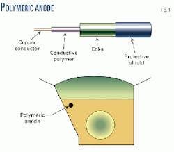
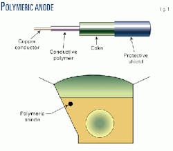
The polymeric anode is constructed in four layers with a copper conductor in the center that is coated with a conductive polymer, surrounded with coke that is kept in place with a porous shield (Fig. 1).
During service, the coke reacts with water and forms carbon dioxide together with hydrogen gas.
C + 2H20 -> CO2 + 4H+ + 4e-
The consumption of coke is typically 0.2 kg/amp/year. At 50 years of lifetime, the anode can deliver 0.02 amp/m of length. To avoid shielding of CP current on the opposite side (Fig. 1), it is very important to install the polymeric anode at correct and specified distance from the pipeline.
The anode is connected to rectifiers at each end to avoid loss of protection in case of anode rupture.
One of the most important issues in selection of a rectifier for the pipelines was the ability to regulate and control the protection level at very low current output. Due to the relatively short lengths to be protected and the good coating quality, very little current demand is experienced on most of the pipelines.
The following specifications are valid for the rectifiers:
- Ceiling voltage of 50 v (DC).
- Ability to regulate at low current output (less than 0.5 amp).
- Instrumentation for online monitoring.
- Automatic or manual constant current and voltage regulation.
- IP 65 required for outdoor installation.
- Protection against surge on the power supply and the DC circuit.
CP test station
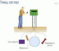
The buildup of a typical test post in a CP system is shown in Fig. 2. The configuration wanted on Statoil's systems consists of the following components:
- Reference electrode (Cu/CuSO4).
- Polarization probe:
- Reference electrode (Cu/CuSO4 or SCE).
- One steel coupon for measurement of free corrosion potential.
- One steel coupon connected to the pipe.
- Test coupon, coated with a defined area of bare metal.
Reference electrodes, probes, and coupons are to be buried in the same backfill as the one surrounding the pipeline.
Test posts are evenly distributed along the pipeline. Maximum distance between two test posts is 2 km.
The following types of measurement can be performed at each test post:
- On-potential of pipe, probe, and coupon.
- Off-potential of probe and coupon.
- Corrosion potential of probe.
- Protection current to probe and coupon.
Online monitoring system
Statoil operates pipelines widely spread in Norway and Europe. Inspections of the cathodic-protection systems are costly and with the increasing focus on cost reduction, especially travel expenses and out-of-office time, we have found it necessary to initiate and install a computerized online monitoring system.
The system is now in operation on all the pipelines in Norway. The idea is that the personnel responsible for cathodic protection can log on and check the status for every pipeline from an office or from a portable computer equipped with a modem.
Especially tuning the rectifiers for better performance is made easier and cost efficient with this system. Regulating cathodic protection levels is time consuming because of the slow kinetics of the electrochemical systems. Earlier, several inspections had to be carried out to tune the rectifiers. Today this can be done from the office.
Also, inspections are made easier with this system.
During an inspection, findings may lead to a desire for a change in rectifier output or starting the rectifier current interrupter. Use of a portable computer, a mobile phone, and a modem can allow this immediately without hours spent in the car or on foot along the pipeline route.
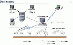
The schematic of the monitoring system is outlined in Fig. 8. Measurements from the test post are collected in each rectifier, digitized, and sent to an online control unit. The control unit monitors and controls the rectifier's output based on information retrieved from the test post.
Three modes of operation are possible:
- Automatic regulation. Rectifier output regulated based on potential measurements from one or several test posts.
- Manual regulation. Constant voltage output.
- Manual regulation. Constant current output.
Alarm limits can be set on all the measured values, rectifier output, or potential measurements from the test posts.
Maintaining integrity
The overall objectives of an integrity-management plan for pipelines are to protect the safety of the public and company employees, protect the environment and private property from damage, and maintain the reliable operation of the pipeline system.
For these goals to be achieved, the pipeline must be protected against both external corrosion and cracking. All pipelines are unique in terms of operational and environmental characteristics, and the appropriate level of surveillance may vary from one pipeline system to another.
Coating damages should be repaired to sustain adequate protection of the pipeline. Half-yearly and annual inspections of test posts and rectifiers are insufficient.
In addition, a long-term inspection and maintenance plan is required, including implementation of close-interval surveys to provide a detailed overview of protection potentials and coating damages along the entire pipeline.
Hence, the integrity of our buried pipelines with respect to external corrosion should be founded on the following activities:
- Routine inspection program. The routine inspection program, involving quarterly or half-yearly inspection at test posts, is used for continuous evaluation of the protection potential and control of the rectifiers' output.
Any increase in the current demand is evaluated with respect to possible coating damages.
- Close-interval surveys. Close-interval surveys using direct-current voltage gradient (DCVG) or close-interval potential survey (CIPS) shall be performed every fifth year to locate possible coating damages.
If coating damages are detected, these must be examined with respect to size and protection potential. Disbonded coatings shielding the CP current (for example, polyethylene shrink sleeves) cannot be detected by these methods.
- Revision of CP system. After completion of the close-interval survey, a revision of the pipeline and CP system is carried out. The purpose of the revision is to develop a plan for upgrading of the CP system and repairing of coating damages.
- Stress-corrosion cracking (SCC) evaluations. The following conditions are key factors for the establishment of the risk for SCC failures:
- Abnormal high or low internal pressure.
- External forces acting on pipeline (earth movement, heavy rains or floods at creek crossings, third-party encroachment etc.).
- Incorrect CP level (telluric current, CP system out of operation, interference, so forth).
- Observations of coating damage or disbondment.
- Findings indicating deviation from specifications.
Computer-aided system
As shown in Part 1 (Fig. 1), the pipelines are spread widely across Europe and thereby also the people involved in the inspection and maintenance operation.
Due to the geographical diversity, getting the right information to the right person can be a problem. Lately, Statoil's Intranet has made it possible to share information electronically in a simple manner.
In order to deal with the information problem, two separate software programs, further described below, have been developed.
The use of the information system is also giving time and cost saving benefits regarding precautionary actions and in reporting to the governmental authorities.
- Reporting database. The intention of the database is to act as a tool for maintaining pipeline integrity with respect to corrosion.
Using this database enables access of information from overview reports and down to a specific potential measurement at a specific test post.
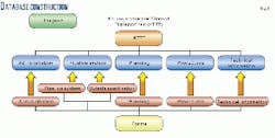
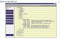
The database is built around five different areas (Figs. 4 and 5):
- Administration: keeping information of contact persons, responsibilities, filing and handling of information.
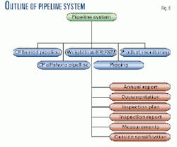
- Pipeline system: Results and evaluation of results from different types of inspection and measurements. Recommendation and outside specification reports are filed here. This database view is further described in Fig. 6.
- Planning: Updated long-term plans regarding inspection and revision of the different pipelines. Any other planning related to corrosion integrity.
- Procedures: Procedures relevant to maintenance of corrosion integrity.
- Technical information: Information unrelated to any specific pipeline system.
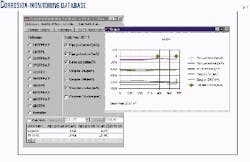
- Corrosion-monitoring database. For evaluating and storing the measurements from the CP inspections, a corrosion-monitoring database has been developed. The database enables the user to:
- Input new measurements.
- Plot measurements with respect toz time.
- Plot the potential profile along the pipeline route.
Files generated from this software are stored in the reporting database, described above. Fig. 7 gives an overview of this software together with an example of the plot function.
