Environmental concerns govern design of UK gas-fired power plant
Design and construction of the Scottish Power generating station at Knapton, North Yorkshire, placed environmental considerations ahead of economic ones in important process decisions.
The result is a plant that was installed in some of the most sensitive areas of the UK countryside without damaging the environment and with minimal impact on the local community.
The 42-Mw generating station produces power for export to the national grid and is fueled by natural gas from four wellheads in the Vale of Pickering. Gas moves to the power plant where an RLM6000 gas turbine set is employed for power generation.
The level of nitrogen oxide emissions from the gas turbine combustor was optimized in line with BATNEEC (best available techniques not entailing excessive cost) requirements.
Extensive landscaping was employed to hide the plant completely, and noise-dampening methods were used extensively, all with the aim of reducing the plant's impact on the local environment.
The proximity of a local tourist attraction prompted a great effort to minimize plant emissions to atmosphere. This involved carrying out a detailed environmental impact assessment that used rigorous dispersion models to identify potential concentrations of sulfur dioxide and nitrogen oxide emissions.
Prompted by the fast-track timing of the project, the plant was designed and built as a series of modules. This approach minimized any risk to schedule by maximizing the time available at site for civil work prior to commencement of mechanical work.
With this reduction in field construction time, the time required for mechanical completion, commissioning, and start-up was dramatically reduced compared to industry norms. The
Gas source
Developed in conjunction with a consortium of gas exploration and production companies, the plant is owned by UK utility Scottish Power for export to the Northern Electric distribution system. Tullow UK Gas Ltd operates the site on behalf of Scottish Power.
Basic design, detailed design, procurement, construction, and commissioning was carried out by Costain Oil, Gas & Process Ltd., Manchester.
The plant is fueled by natural gas extracted from deposits under the Vale of Pickering via four existing wells (Fig. 1). The gas lies in four reservoirs trapped in two types of rock.
Most of the gas lies in Permian-age limestone at a depth of 1,200-1,500 m. The gas exploited from this reservoir is sour. The remaining gas is sweet and lies in Carboniferous-age sandstone at a depth of 1,500 m.
Separation equipment is supplied at each wellhead to remove any liquid produced with the gas. Gas from each site flows into an 18-km, 150-mm, nominal-bore buried pipeline which combines the gas produced at each site and delivers it to the power plant at Knapton.
Normally no more than two wells are on line feeding the gas turbine at any one time, although the design allows all four to be used simultaneously.
Produced water from each wellhead and liquid hydrocarbons are separated from the gas at the power plant and re-injected into the gas reservoir via a fifth well. The liquid effluent from the power plant is conveyed to the reinjection well via a 75-mm liquid return line running parallel to the gas pipeline.
In order to protect against hydrate formation and corrosion of equipment and pipelines, glycol and corrosion inhibitors are added at each well site.
Gas arriving at the power plant requires conditioning to specification before being fed to the gas turbine. This involves temperature and pressure regulation, condensed liquid removal, control of sulfur content, particulate removal, and fiscal metering.
The nature of the project results in many unit operations being used on the Knapton power plant, including:
- Demineralized water production.
- Gas-turbine electricity generation.
- Glycol recovery.
- Advanced control and communication systems.
To minimize any environmental effect on the surrounding countryside, fugitive emissions were eliminated wherever possible, noise levels met stringent guarantees, and landscaping reduced visual impact.
Vale of Pickering
The Vale of Pickering lies in an area of outstanding natural beauty, bordered by the North Yorkshire moors national park, the Howardian hills, and the Yorkshire Wolds.
The environmental sensitivity of these surroundings led to investigation of an area of 608 sq km that identified potential zones with the least environmental impact and lowest sensitivity to development.
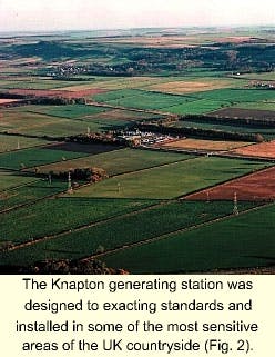
The chosen site is on farmland and has the advantage of being bordered on three sides by mature plantations that would provide natural screening, with the potential to reduce the visual impact further from the exposed side by further planting (Fig. 2).
Furthermore, the site is remote from housing and has the advantage of being only 400 m from existing electricity transmission lines. Also, the quality of the landscape was already reduced by the presence of electricity pylons and a railway line.
Before construction could begin, the Environment Agency (responsible in England and Wales for pollution prevention and control) had to be convinced that the project would not harm local wildlife and cause minimum disruption to its surroundings.
An archaeological survey of the area revealed evidence of Bronze Age and Iron Age land use and a medieval settlement. As a result, some changes had to be made to the pipeline routings to conserve sites of potential historical interest.
During the construction stage, some items of archaeological interest were discovered and lodged in the Malton Museum.
A further interesting feature of the project planning stage was the requirement to acquire access rights over the land that the pipeline traversed, one of the owners being Her Majesty's Duchy of Lancaster.
A planning application for the North Yorkshire Power Project was submitted in 1990, accompanied by the site selection survey, environmental statement, and safety evaluation.
As a result, the Secretary of State received more than 800 objections to the development by individuals and organizations.
A public inquiry was held in 1992 that addressed many of the objections. Planning permission for the generating station, associated pipelines, wellheads, and overhead transmission lines was granted in March 1993.
A major part of the project involved satisfying the local community, other groups, and regulatory authorities that every effort would be made to reduce the environmental impact of the project. This involved engineering to BATNEEC standards to convince the Environmental Agency to allow construction of a power plant in such a sensitive area.
The environmental requirements were extremely stringent so as to have minimal impact on the high air quality of the area and cause no disruption to the local economy, largely agriculture and tourism.
An additional feature of the Knapton development was a high degree of community liaison, enabling exchange of information and opinion.
Approaching the project in this manner helped assuage the fears about the development from the various groups involved. This open dialogue kept various groups informed and, more importantly, made apparent the lengths to which both client and contractor were going to minimize environmental impact.
The gas-turbine generating set was identified early in the project as a long lead item to be ordered early in the design to ensure timely completion of the project. A design freeze on the turbine fixed design early, allowing time for procurement to be completed.
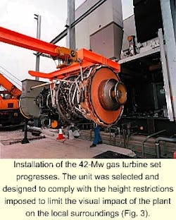
The turbine chosen, the RLM6000, supplied by European Gas Turbines, now called ALSTOM Power, was specified as low-NOx producing to meet project requirements of minimizing emissions (Fig. 3).
Installation of the pipelines from the wellheads to the process plant involved many complicated and hazardous operations. In addition to river, road, and rail crossings, it was necessary to cross an existing high-pressure (HP) gas line.
To reduce disruption to the tourist season, thrust-boring rather than cut-and-fill techniques were employed for the road and rail crossings. This enabled the work to be carried out while the transport systems were still in service.
Wellheads
Gas is produced from four underground deposits and flows to the surface at reservoir pressure. Each wellhead has the potential to produce a large amount of liquid that flows to the surface with the gas.
The liquid is a combination of water and condensate, with large quantities of salt. Separation equipment is supplied at each wellhead, with liquid waste being collected for reinjection down a fifth well.
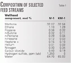
Table 1 gives typical gas compositions; these are design figures with the actual sulfur levels considerably lower.
The figures shown relate to gas produced from two of the wells, KM-1 and M-1. The high-sulfur content in the stream from wellhead M-1 is typical of the design levels used at each of the sour deposit wellheads.
Each well site is provided with a glycol-injection unit and a corrosion-inhibitor package. Mono-ethylene glycol is injected into the vapor outlet from the wellhead separators to prevent formation of hydrates as the gas passes down the pipeline.
Glycol also aids corrosion inhibition by removing any free water. The corrosion inhibitor is required to protect the gas and liquid pipelines from the more-aggressive components of the process stream: hydrogen sulfide, mercaptans, and carbon dioxide in significant concentrations.
A common design was used for each of the wellheads, allowing easy transfer of equipment to other wellheads or re-use of existing equipment upon discovery of new gas deposits.
This design allowed for a maximum equipment height of 4 m, thus minimizing the impact of the sites on their surroundings.
Pipelines
Gas production and pipeline management are controlled by the well site priority system from supervisory control and data acquisition (SCADA), which provides remote monitoring and operating of the main plant and its associated well sites.
The SCADA system incorporates sophisticated leak detection used to detect fugitive emissions from the pipeline.
The need to detect and eliminate fugitive emissions is clear when considering the consequences of adverse publicity. The odor from even a few parts per million of H2S is very distinct, and incorporating leak detection was warranted, even though the quantity of escaping gas was harmless.
Incorporating the leak-detection system is one of many examples of environmental considerations outweighing economic ones in the design of the Knapton power plant.
Design of the system is such that gas may be taken from any combination of the four well sites and used to meet the requirements of the gas turbine.
The turbine requires a minimum suction pressure of 42.5 barg for satisfactory operation. As each well will vary in pressure throughout its lifetime, a choke valve is installed at each well site, allowing the operator to produce a uniform pressure throughout the gas supply system.
The wellhead pressure at the start of production varied between 75 barg and 148 barg across the four wells. Over the life of the plant, the wellhead pressure will deplete. Hence, the pipelines were designed to operate between 70 barg at the start of production, falling to 55 barg towards the end of the well's life.
Reservoir management is controlled from the plant control room so that any of the wells may be selected according to priority. Should one of the well sites have an operational problem, then the next well site in the priority system will automatically start production.
British Gas' standard pigging equipment is provided at each of the wellheads and at the power plant to remove any build up of liquid in the pipelines.
Liquid is produced in the pipeline between the wellheads and the power plant, due to pressure drop in the line. This waste liquid is removed upon reaching the power plant and re-combined with condensate separated at the wellheads.
The liquid passes to the reinjection module, where it is fed into a separator vessel. Vapor from this vessel then flows back into the gas pipeline, and the waste liquid is filtered before being re-injected down the fifth well.
Disposing of the liquid waste in this way avoids the need for costly treatment procedures and ensures the waste will not find its way into the local environment.
Pipeline construction involved rail, road, and river crossings. Crossings were carried out on in-service transport routes, minimizing disruption to the local tourist industry.
Process plant
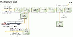
Gas arrives at the power plant from the pipeline and must pass through a series of unit operations before it is suitable to be fed to the gas turbine for power generation (Fig. 4).
Sulfur emission rates on the power plant are currently controlled by blending sour gas with sweet gas before combustion in the gas turbine. Sulfur removal, by injection of scavenger chemicals into the gas stream, is currently under investigation.
Upon reaching the power plant, the gas enters a slug-catcher module that is predominantly used during pigging operations to catch large slugs of liquid. This vessel is designed to provide buffer capacity to protect plant operation from a large slug of liquid from the pipeline.
Both the gas and the liquid streams from the slug catcher are passed to the knockout drum, which acts as a three-phase separator efficiently to remove liquid droplets from the gas stream using a high-efficiency demister pad.
The internal arrangement of the knockout drum allows the separation of the condensed hydrocarbon from the dense glycol-water phase. The hydrocarbon phase is fed under level control into the closed drain system, while the dense glycol-water phase is fed under interface control to the glycol recovery unit (GRU).
The gas turbine requires gas with a minimum of 10
The feed gas to the turbine is heated prior to pressure regulation to prevent the formation of hydrates upon stream cooling.
After pressure regulation, the gas stream passes through a fiscal metering station. This system meters all gas arriving at the power plant, including plant fuel requirements and gas diverted to flare.
The system consists of an ultrasonic duty flow meter with a turbine meter supplied as back-up. Accurate filtration, pressure, and temperature readings allow the computation of flow at standard conditions, giving the meters an accuracy of
Glycol recovery is provided at the power plant to recover the glycol injected into the gas streams at each well site. Feed to the glycol-recovery unit is the dense glycol-water phase separated in the plant knock-out drum, the unit being designed to remove any water and entrained hydrocarbons to render the glycol suitable for reuse at the well sites.
The feed to the GRU is dropped in pressure in a horizontal three-phase separator, and any gas produced is removed here. (Most of the entrained hydrocarbon liquids will flash and be removed at this stage.)
The flashed off vapor then passes to the closed drain system for disposal. The glycol stream passes through a series of filters and is heated by interchange with the hot product glycol in the glycol accumulator before entering the still column.
The glycol regeneration system consists of a packed column, a glycol reboiler, and a glycol accumulator. The packed column contains a bed of stainless steel pall rings and has a stainless steel condenser coil through which the feed to the unit is passed.
The glycol reboiler is a 25-kw, internally mounted immersion heater; hot product glycol flows from the reboiler to the glycol accumulator.
A fin-fan cooler cools the waste gases from the still column. The vapor and liquid produced are then separated by the overheads drum and passed to the closed drain-vent system.
The glycol product from the accumulator is cooled in a fin-fan cooler before passing to the glycol storage tank. The product glycol is stored here until it is ready for returning to the well sites via road tanker.
Liquids produced by the various unit operations on the Knapton site are sent for disposal to the closed drain system. There are permanent feeds to drain from the glycol-recovery unit, the plant knock-out drum, and the demineralized water unit.
Other feeds occur during equipment venting and draindown.
The closed-drain system then empties into the vent knock-out drum. Any vapor present is passed via the low-pressure (LP) header to the LP burners of the flare system.
Waste liquid is pumped, under level control, from the knock-out drum to be reinjected at the wellhead.
Power generation
Before entering the gas turbine, the gas enters the turbine inlet knock-out drum where any remaining liquid droplets are removed.
Filter separators are the last stage of treatment before the gas enters the turbine. These filters are designed to remove all but the smallest particles and liquid droplets.
From this module, the gas passes to the turbine.
The gas-turbine generator set is the principal unit at the power plant. The machinery train consists of one gas fuel turbine electric set with water injection, driving a machine-geared AC generator set.
Demineralized water is injected with the fuel to lower the temperatures in the combustion chamber. When the combustion chamber runs at high temperatures nitrogen gas is converted to NOX that is subsequently released into the atmosphere.
The water added to the turbine must be demineralized, as sodium and lithium salts damage the turbine blades.
The gas turbine is housed in its own acoustic enclosure to limit noise pollution. Ambient air is drawn into the gas turbine air intake, filtered, and then compressed by the LP and HP compressors to the required ratio.
The air is then mixed with the fuel and the resulting mixture burned in the combustion chamber. The hot gas leaving the combustion chamber passes though the HP turbine stages in order to drive the HP compressor, then passes through the LP turbine stages in order to drive the LP compressor.
The spent gas is routed through a silencer and discharged to atmosphere through an exhaust stack.
A height restriction of 15 m was imposed on the power plant, intended to reduce the visual impact of the site on its surroundings. The project need to limit the visual impact of the plant had the effect of driving the selection of the gas turbine generator set.
Thus, equipment selection was not based solely on price, but also on which manufacturer could supply the generator to the required environmental specifications.
Utilities
Demineralized water is required at the power plant for injection into the gas-turbine combustion chamber that suppresses NOx formation by lowering the combustion temperature.
Town water is fed to the demineralized water unit, housed in a specially heated enclosure, for salt removal. From here, the demineralized water is kept in a storage tank sized to provide a 24-hr reserve.
A ground incinerator is provided at the power plant to flare off any gas produced as waste or due to occurrences of relief, emergency shutdown, or depressurization. The ground flare is staged to make combustion of waste gases more efficient.
The flare has both LP and HP systems, with the LP system used to incinerate small effluent vent flows and the HP system sized to handle the entire flow of gas arriving at the power plant.
The incinerator is designed to meet stringent environmental constraints, including low NOx production, low emission levels of uncombusted hydrocarbons, odorous compounds, and stringent noise constraints.
The flare is specified to fall under the maximum allowable height of 15 m, and a ground flare was selected to produce no visible flame. Regular testing of the flare ensures continued efficient combustion and identifies any emission problems early.
A 40% glycol-water mix is used as heating medium on the power plant. This is necessary to heat the fuel gas to the correct temperature before pressure let down. The heating medium is also used to maintain the temperature in the de-mineralized water unit housing, preventing freezing in low ambient temperatures.
The heating medium system uses a fired-heater arrangement, designed specifically to achieve low NOX emissions through the burner arrangement.
Nitrogen is supplied on site via road tanker and stored until ready for use. The glycol storage tank requires a constant inert atmosphere as contact with air causes degradation to the glycol. A small purge is also required on the HP stage of the flare to maintain a positive flow to atmosphere.
Instrument air is required on site for all pneumatically operated valves and is also used in the gas turbine for cooling purposes on emergency shutdown. The instrument air system is supplied as a packaged unit.
Environmental
The Knapton power plant is designed to avoid any complaints by persons outside plant areas. To this end, stringent constraints have been laid down in the following areas:
- Odorous emissions.
- Discharge to sewer.
- Noise.
- Visual impact.
Steps taken to address these requirements have been given previously. In addition, however, it was necessary for several further actions to be taken during and after design.
Fugitive emissions have been eliminated wherever possible in the power plant and at each of the wellheads. This has been achieved by the correct selection of valve packing and flange gaskets and a detailed study assessing the impact of any emission.
Regularly testing the background levels of sulfur and other pollutants ensures that these standards are maintained.
In addition to the closed-drain system for all liquid waste from the site, all surface water is collected and analyzed prior to discharge to local drainage systems.
The plant is designed to meet stringent noise constraints so that people living in the local area are not unduly affected. Noise dampening methods have been applied to all valves and acoustic enclosures have been used for major equipment items.
The visual impact of the power plant was always a sensitive issue because of the surroundings of the site. A height restriction of 15 m is observed throughout the power plant. The color scheme of the plant was specifically chosen to blend with the surroundings, with green, black, and brown predominantly used.
An artificial embankment around the site was constructed, and approximately 20,000 fast growing conifers were planted to disguise the area further.
Project features
Basic engineering required the conceptual design to be developed to meet the stringent requirements of the latest environmental legislation. This meant satisfying the requirements of Her Majesty's Inspectorate of Pollution, the National Rivers Authority, and the Health & Safety Executive, among others.
The SCADA system provides a means of monitoring and operating the main plant and its associated well sites. The system consists of seven remote terminal units, one located at each well site, one in the control room, and one in the switch room.
These RTUs communicate with the master station, giving data in the form of trends, alarms, and events that can be called up at any time. The RTUs at the well sites are responsible for gathering information and controlling that area.
The two RTUs on the main plant are responsible for the control and display of all the data relating to pumps and drives throughout the plant as well as controlling the ESD system and prioritization of the plant instrumentation.
All communications on site are controlled with both fiber-optic and radio links.
To ensure the maximum time to facilitate site clearance and civil works, the plant design was laid out in a modular format and built up as a series of preassembled units.
Preassembly in this way reduced the mechanical and electrical aspects of field construction.
Manufacturing the plant in the form of preassembled units allowed much of the work to be done in controlled workshop conditions, unhindered by the weather, giving maximum quality control.
The authors-
Mike Healy is process-engineering manager at Costain Oil, Gas & Process Ltd, Manchester. Previously, he worked for MW Kellogg, London. Healy holds a BSc in chemical engineering from Nottingham University and is a fellow of the Institution of Chemical Engineers and a chartered engineer in the UK.
Graeme Wilson is a process engineer with Costain Oil, Gas & Process Ltd., joining in 1996. He holds a BEng in chemical engineering from Heriot-Watt University, UK, and is an associate member of the Institution of Chemical Engineers.
Cathy Dufton is a senior process engineer with Costain Oil, Gas & Process Ltd. She has 7 years' experience in front-end and detailed design of oil, gas, and petrochemical facilities. Dufton is a chartered engineer and holds an MEng in chemical engineering and environmental technology from the University of Manchester Institute of Science and Technology.
