Varied pipeline conditions complicate mitigation strategies
CORROSION MANAGEMENT-1
Statoil has initiated a comprehensive, pipeline-integrity management system for corrosion protection of buried onshore pipeline systems, taking into account the unique operation and environmental characteristics of various systems.
The flexibility of Statoil's program makes it a good candidate as a best practice for developing inspection and maintenance manuals for other onshore pipeline systems.
Differences in environmental conditions, such as soil resistivity, and differences in infrastructure present several interference problems. Statoil also takes various operating conditions into account when it considers the appropriate protection for the system, such as coatings, procedures to mitigate stress corrosion cracking, or cathodic protection.
The technical challenges during construction and service are related to highly variable soil resistivities, very low pH marshes, AC and DC stray currents, and telluric currents.
This is the first in a series of two articles documenting Statoil's best practices for buried-pipeline integrity management. This article describes the company's different pipelines and the variety of challenges each system experiences.
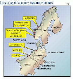
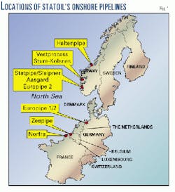
Most of the pipelines operated by Statoil are short onshore sections of major offshore trunklines. The pipelines are located in Norway, Germany, Belgium, and France (Fig. 1).
The concluding article in this series will describe the online monitoring system, inspection and maintenance philosophy, and the computer-aided information system used by Statoil.
Statoil systems
The general terrains for Statoil's pipelines in Norway, Germany, Belgium, and France differ. Hence, Statoil applies varying corrosion control to each environmental condition based on the general conditions of each pipeline system.
Norway
The pipelines in Norway include the following systems:
- Statpipe, with both 28 in. (700 mm) and 30-in. pipelines, has been in operation for 15 years.
- Sleipner condensate (20 in.) has been operating for 5 years.
- Haltenpipe (16 in.) has been operating for 3 years.
- Åsgard (42 in.), Europipe 2 (40 in.), and Vestprocess (16 in.) are new pipelines.
Typical Norwegian pipelines sit in rocky ground with a high resistivity and isolated marshes and small lakes. Heavy rains on the west coast of Norway give these areas different pH (acid rain) and wet and dry conditions.
These pipelines, therefore, have highly variable conditions regarding resistivity and pH in the trench, which leads to a variable current demand. Traditional cathodic protection (CP) systems based on anode ground beds and rectifiers have proven insufficient in these areas.
The land sections of the Norwegian pipelines are influenced by telluric currents as well as AC interference caused by high-voltage power lines.
Other countries
The pipelines in Germany include the land sections of Europipe 1 and Europipe 2. The condition of these pipelines, with the help of cathodic protection, is good.
Most of the German pipelines are below the water table in a soil with reasonable resistivity.
The pipelines in Belgium and France are below the water table but in a sandy soil with high resistivity. The pipeline in Belgium is influenced by stray currents caused by the trains and trams in the area. It is also electrically bonded to existing pipelines of the Belgian network.
In France, the pipeline passes through an area of heavy industrial activity with several buried pipelines with other CP systems. Bonding and stray currents are the main problems in Belgium and France.
Interference challenges
Geomagnetically induced currents (GICs; also called "telluric currents"), direct currents, and alternating currents cause interference problems which challenge pipeline integrity.
GICs are most pronounced on the Norwegian western coast. DC interference from tram and railway systems in central Europe, and AC interference from overhead parallel high-power transmission lines are also items of concern.
GICs
Shortly after Statpipe was laid in 1985, inspection of the CP system revealed large potential fluctuations that could not be explained by normal AC-DC interference phenomena.
After a study of the electrochemical potential fluctuations and after several discussions with universities and other pipeline operators, Statoil identified the potential fluctuation to be related to GICs.
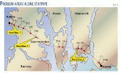
Fig. 2 outlines the pipeline route: about 20 km long with total buried distance typically of 8 km in normal terrain and 12 km in tunnels at the fjord crossings.
Statoil identified several questions pertaining to GIC:
- How is the potential fluctuation distributed along the pipeline?
- Is there really a correlation between GIC and the on-potential fluctuations?
- Does Statoil experience a similar fluctuation on the off-potential?
- Is there current flow to and from the pipeline?
- What are possible mitigating effects from grounding?
The most important question was the behavior of the off-potential. If potential fluctuations occurred during a GIC incident, they could cause flow of current from the pipeline, inducing corrosion.
Statoil focused on the western part of the pipeline route. In addition to existing installed polarization probes, the company connected new steel coupons to the pipe and buried them in the ground.
And it conducted all measurements related to off-potential and flows of current on polarization probes or steel coupons.
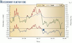
The most interesting part of this recording was the flow of current. Fig. 3 reveals that the flow of current to the steel coupon was reversed when the on-potential became more anodic than the off-potential.
Even if the off-potential were more cathodic than the limit of -0.85 v, the monitoring shows that corrosion can occur.
The corrosion risks on pipelines generally depend on the anodic current densities during the GIC periods and the number of GIC incidents. The anodic current has been measured up to 1.2 ma/sq cm.
Statistics from the geomagnetic metering stations in Norway show that the number of GIC incidents at this magnitude was 400 in 1989. The number steadily dropped to about 200 in 1995.
Solar activity increased every eleventh year. Reported activities from the metering stations represent a half cycle of the 11-year solar-activity period.
Statoil assumed an average of 300 GIC incidents/year to estimate an average corrosion rate from GIC of 0.03 mm/year. For a pipeline with 50 years of service, the total corrosion metal loss will thus be 1.5 mm.
It is difficult to estimate the depth of attack from local corrosion. Local corrosion depths can be at least 2 or 3 times the uniform corrosion depth.
To mitigate the possible risk of corrosion, Statoil is considering installing proper electrical grounding at each pipeline end. This action will ground the GIC in a controlled manner, avoiding corrosion damage.
AC interference
Several distribution companies have reported that AC interference from high-power transmission lines causes corrosion problems on buried pipelines. AC interference can also represent a health risk during construction and service of the pipeline and CP system.
Statoil has two guidelines to eliminate health risks and prevent corrosion:1
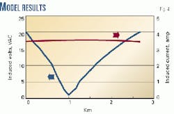
To eliminate health risks, the induced AC voltage shall not exceed 15 v. The AC voltage is measured between the pipe and a remote reference electrode.
To prevent corrosion, AC shall not exceed 20 amp/sq m.
AC-interference considerations are mainly in reference to a 42-in. pipeline. The pipeline is laid in parallel with two high-power transmission lines operating at 200 and 300 Mw, respectively.
The distances between the pipeline and the transmission lines vary from 10 m to 400 m with a total length of about 2 km. The transmission-line towers have grounding electrodes to prevent failure from fault currents.
To investigate the potential AC-interference problems related to this pipeline, the company used a modeling program developed by the American Gas Association and Pipeline Research Council International Inc.2
As shown in Fig. 4, the model indicated that the induced voltage exceeds the limit of 15 v (AC). The induced current, however, only reaches a value of 3.5 amp. These values indicate that the risk of corrosion from AC interference is moderate and only minor mitigation effort is necessary.
The pipeline continues in the sea on both sides of the area in question, across two fjords. During evaluation of the possible corrosion problem, Statoil identified that AC first of all will be earthed from the pipeline at the sacrificial anodes in the seashore areas. The magnitude of AC is such that the company expects increased sacrificial-anode consumption.
External coatings
Statoil has used different types of coating for its buried pipelines.
The oldest pipeline (Statpipe) is coated with factory-applied asphalt enamel. The field joints were coated with heat-shrink sleeves after being blast cleaned.
All other Statoil pipelines have used the newly developed three-layer, fusion-bonded epoxy (FBE) and polypropylene (PP) coating system. This system is based on the following specification:
- Blast cleaning to Sa 21/2.
- Application of 300 mm FBE.
- Application of a polypropylene copolymer as adhesive.
- Application of polypropylene topcoat with a thickness dependent on diameter and operating conditions.
Coatings specialists simultaneously cure all layers to form an integrated coating system. The polypropylene films are typically 2-4 mm thick.
Proper surface pretreatment of the steel is essential for optimal performance of any coating.
The pipes to be coated are initially washed and heated prior to blasting. Following removal of dust, a surface cleanliness of Sa 21/2 (near white blast cleaning) and salt level of < 10 mg/sq mm is to be achieved before application of the first layer coating system.
The coating systems selected are generally considered to be superior to most systems on the market. The main problem has been to find a compatible field-joint coating system.
For the first pipelines-Zeepipe, Europipe1, and Haltenpipe-Statoil used the heat-shrink sleeve as basically most compatible with its main coating system.
The company was unhappy with this, and some experiences with poor workmanship for application of the sleeves have resulted in a change of philosophy.
Statoil has used a sprayed-on FBE/PP field system for its latest pipeline projects. This is fully compatible with the factory-applied system but very expensive.
Alternatively, it has used a thick (600 mm) FBE system, which is mechanically protected by sandbags or textile wrapping systems.
The primary purposes of using these advanced coating systems are to reduce the current demand by current passing through the coating or at coating defects and to ensure proper protection against stress corrosion cracking (SCC) beneath disbonded coatings.
The three-layer system combines the corrosion protective properties of FBE with the good mechanical protection of polyolefins. Table 1 gives a summary of selected coating systems.
Stress corrosion cracking
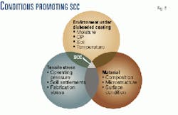
SCC is a type of corrosion that occurs only when several conditions are present simultaneously and fall within limited ranges. In general, three factors are essential in controlling the initiation and propagation of SCC:
- A specific cracking environment.
- Tensile stresses.
- Material that is susceptible to SCC (Fig. 5).
The majority of onshore pipelines have high-integrity coatings (three-layer FBE/PP, extruded polyethylene) providing excellent protection against SCC.
Disregarding the possibility that FBE coatings may eventually prove susceptible (given enough time), it is considered that the focus shall be put on shrink sleeves and pipelines coated with asphalt.
Increased attention to the problem of SCC has arisen during the last few years, particularly related to a number of incidents in Canada since 1985. Extensive field investigation showed that the type of SCC that caused the failures in Canadian pipelines was generally different from the classic SCC that had been observed earlier on other pipelines.
It must however be emphasized that if coating damage allows access of groundwater to the pipe surface and the CP is insufficient or absent, SCC may be possible regardless of type of coating.
Protection criteria
Establishing the protection criteria (appropriate potential range for CP) has been subject of extensive discussions since the method was first adopted. Traditionally, NACE recommendations have been used for buried pipelines.3
During recent years, the European approach has gained more support and is now adopted by the draft CEN and ISO standards and seem to be generally accepted worldwide.4
The new ISO standard for cathodic protection of buried pipelines has adopted the following criteria that now are implemented by Statoil.
The CP system shall be capable of polarizing all of parts of the buried pipeline to potentials more negative than 2850 mv vs. the Cu/CuSO4 (saturated) reference electrode and of maintaining such potentials throughout the design life of the pipeline.
These potentials apply to the metal-environment interface, when the protective current is flowing. For buried pipelines, this value corresponds to the IR free potential.
Other reference electrodes can be used, provided that their properties are reliably derived and adequately documented. For carbon and low alloy steels, the potential at the metal-environment interface should not be more negative than -1,200 mv vs. a Cu/CuSO4 (saturated) reference electrode to avoid the detrimental effects of hydrogen production or a high pH at the metal surface.
For pipelines operating in anaerobic soils and where there are known or suspected to be significant quantities of sulfate-reducing bacteria or other bacteria having detrimental effects on pipeline steels, more negative potentials may be necessary to control external corrosion.
In this case, the recommended protection potential is -950 mv vs. Cu/CuSO4 (saturated) reference electrode.
References
- Gummow, R.A., "Cathodic Protection Considerations for Pipelines with AC Mitigation Facilities," PRC International Corrosion Supervisory Committee, 1998.
- Dabkowski, J., "AC Predictive and Mitigation Techniques," PRC International Corrosion Supervisory Committee, 1998.
- NACE International Standard RP0169, "Control of External Corrosion on Underground or Submerged Metallic Piping Systems."
- ISO Standard, Pipeline Cathodic Protection Part 3: Cathodic Protection for Onshore Pipelines (in progress).
The Authors
Svein L. Eliassen is a corrosion specialist for Statoil. He holds a Siv. Eng. and a Lic. Tech. (Dr. Eng.) in technical electrochemistry from The Norwegian Institute of Technology (NTH), Trondheim.
Sven Morten Hesjevik is a senior engineer at Statoil. He holds a bachelors in engineering from TIH in material science.
