Narrow rain forest ROW forces innovation for Ecuadorian flowline installation
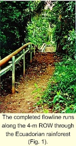
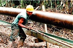
Construction of the Villano flowline in eastern Ecuador has proven that a major pipeline can be built on a 4-m wide ROW through virgin rain forest with minimum environmental impact (Fig. 1).
Built through primary rain forest without roads or heavy equipment, the line was completed in March 1999 after 8 months of construction.
Block 10 development
The flowline is part of the Villano Block 10 development project, carried out for Ecuador's national oil company Petroecuador, ARCO Oriente Inc., Agip Petroleum (Ecuador) Ltd., and their engineering, procurement, and construction (EPC) contractor Fluor Daniel Williams Bros. (FDWB).
Agip has since assumed full operating responsibility for Villano.
Block 10 lies in the west-central section of Ecuador's Pastaza province (Fig. 2).
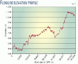
Fig. 3 shows the flowline elevation; the flowline divides into three sections.
- The first section extends through 37 km of rugged, geologically faulted, humid tropical rain forest from the Villano well site to a steep escarpment marking the forest boundary.
- A second section, 1 km, runs from the forest floor to the top of the escarpment, approximately 500 m above.
- The third section, 6 km, continues over hilly terrain through existing farmlands to the central processing facility (CPF).
The last two sections were constructed with normal buried pipeline construction methods on a 10 m right-of-way (ROW).
The flowline consists of 12-in. OD 5LX Grade 65 pipe, internally and externally bare, 0.281, 0.375, and 0.438-in. WT. Design pressure is 1,950 psig, and design temperature is 205° F., with a corrosion allowance of 0.125 in. Design flow rate is 55,000 b/d.
Along the flowline is a power system consisting of three single-conductor, 35 kv, shielded power cables with a No. 2 AWG ground cable. The communications and control link between the well site and the CPF consists of a 24-element fiberoptic cable and six solar-powered valve stations.
Restricted ROW
The problem was to build a pipeline through virgin rain forest with minimal environmental impact. The project management team recognized that reduced impact would depend on carefully controlled construction activities.
Moreover, experience in Ecuador clearly showed that impact could be both direct and indirect. Building a road to move heavy equipment, for example, usually opened isolated areas to logging and cattle ranching, with disastrous consequences for the forest and its native inhabitants.
To address this problem, the team decided to limit right-of-way width along the flowline route to 5 m, far less than the conventional 15-30 m. A wider ROW would also open continuos breaks in the tree canopy and inhibit the movement of arboreal animals.
The decision to use a narrow ROW ruled out conventional construction methods and equipment, such as bulldozers, backhoes, and sidebooms. The team also decided against burying the line because excavation would encourage erosion on steep slopes and damage tree roots. And conventional construction would require a much wider ROW for storing the spoil.
A pipeline built aboveground in a rain forest, however, might be vulnerable to corrosion or other problems. The team decided that this danger was minimal: A combination of hot oil and the lack of direct contact between pipes and soil or vegetation eliminated the threat of corrosion and the need for external pipe coating.
Alternative construction ideas came from Ecuadorian contractors familiar with rain forest conditions and local personnel. One proposal suggested building the flowline with minimal equipment and moving materials along the ROW with an overhead monorail crane system.
This approach called for material-laydown areas and temporary campsites every 3 km along the ROW. Construction materials would be transported by helicopter to these sites.
The monorail would then move pipe, structural steel, welding machines, clamps, welding rods, radiographic testing equipment, lunches, tools, water, and a myriad of other things to the work front every day. It would be needed for approximately 8 months of construction activities and be removed when construction was completed.
The challenge of this approach lay in finding a monorail system that could work well in the tropical forest and could also be built under demanding conditions. It would have to work in the rain (Villano received 15 ft of rainfall during the year of construction), handle 1-ton pipe joints, and be reliable and safe, environmentally benign, capable of moving heavy loads over rugged terrain, and affordable.
Research
Once this construction concept was accepted, an ARCO/FDWB team convened to turn it into reality. Because of delays in finalizing the construction strategy, team members needed to make construction and design decisions normally left to the construction contractor.
FDWB proceeded with detailed engineering for the flowline and cable support system, temporary work camps, and valve station designs. Designs were needed quickly so that materials and equipment would be available when the contractor was selected.
A team group traveled to Europe, where it investigated possible construction equipment and transportation systems. Of primary importance, this group was looking for tractors to be used in clearing and grading the ROW, as well as pile-driving equipment and an appropriate material-transport system.
Several lightweight, heli-transportable, walking excavators were identified as capable of working in the difficult Villano terrain. Eventually, the team chose an X4M Turbostar (8,500 kg GVW) manufactured by Kaiser Fahrzeugwerk AG, Liechtenstein.
With its 6-ton winch, wide tires, and movable legs, it was ideal for the 45° slopes and mud of the jungle. This excavator came with a standard bucket attachment. Shear and pile-driving attachments not available as standard accessories were specifically designed and manufactured for the project.
With these modifications, the walking excavator was capable of clearing, grading, and pile-driving operations. Six of these machines were ordered for rapid delivery to Ecuador.
The team did not find an overhead monorail system capable of working on Villano's slopes. Instead, it found a top-running monorack system manufactured by Nikkari Ltd., Okayama, to transport wine grapes over hilly terrain.
This technology, based on the cogwheel-train principle, was adapted to agricultural applications more than 25 years ago. It was suitable for rain forest terrain but was built to carry a maximum 250 kg load; each joint of pipe, however, weighed 1,000 kg.
Several adjustments (increasing horsepower, strengthening the chassis, and increasing breaking capability) were made to modify the standard system and an order was placed.
While design and procurement were under way, five construction bidders made a site visit. This trip convinced several of them that the rain, mud, helicopter logistics, difficult terrain, and unorthodox construction technique would make the job too risky to undertake.
Only two of the five submitted viable bids and both were more expensive than expected. After long negotiations, a Brazilian company, Companhia Nacional de Dutos (Conduto), Rio de Janeiro, was awarded the flowline construction contract.
Staged construction
From the beginning, management team members recognized that construction was going to be very labor intensive. At peak levels, Conduto employed 510 people in the field.
To meet this demand, local workers were trained to perform most activities. For example, indigenous workers exclusively from local communities carried out clearing, grading, monorack installation, and cable handling.
Flowline construction involved several stages:
- The right-of-way was cleared and the monorack erected.
- Prebent pipe sections were flown by helicopter to designated staging areas.
- Pipe was moved by monorack to the stringing front where it was hoisted onto H-frame supports and welded into place.
Here is a more detailed description of this process:
ROW clearing, grading
Team members were committed to keeping the forest canopy intact. This goal was met in two ways by surveying a ROW that avoided larger trees and by carefully cutting smaller trees so that attached vines wouldn't drag down other vegetation.
A machete crew first cleared the ROW of brush and small trees, followed by a walking excavator with hydraulic tree-shear attachment (Fig. 4). This attachment allowed the tractor to grasp trees up to 30 cm in diameter that were then cut and lowered to the ground.
Another walking excavator with a standard bucket followed the clearing crew to complete ROW preparation. Remaining brush and small amounts of topsoil were removed and piled to the side for reuse after the pipeline was installed.
At first, this process produced a 4-m wide ROW, but practice and experience later limited it to 3.5 m in most sections.
Campsites
Thirteen campsites were spaced approximately 3 km apart along the 37-km ROW so that the furthest distance from a camp to the work front would be 1.5 km. The monorack traveled at 2.5 kph, meaning a roundtrip of 1 hr and 20 min to the farthest point.
Campsites averaged 4,000 sq m including the camp itself, a material laydown area, pipe-bending area, and a helicopter pad. To minimize the camp footprint, two-story transportable buildings were specially designed and transported by helicopter.
Each camp included two dormitories with eight rooms, an office-medical-supervisors' quarters with four bedrooms, a two-story kitchen-storage building, and a single-story bathhouse.
In all, 72 people were housed there. As flowline construction progressed, campsites were revegetated and buildings were moved to new work areas. Only six sites remain in use as permanent valve stations.
Pile driving; H-frames
The pipeline rests on H-frames fabricated of galvanized structural steel I-beams (Fig. 5). A third walking excavator fitted with a Delmag D-2 (1,800 ft-lb) pile-driving hammer drove the piles to refusal at an average depth of 2.5-3 m.
The aboveground height of the installed pipeline was established at 1 m nominal (45 cm minimum) which was efficient for welding crews, kept vegetation away from the pipeline, and allowed the cable tray to be installed underneath the pipe.
At a number of locations, the pipe was intentionally raised higher off the ground to allow for trail crossings. H-frame installation averaged 150 m/day after crews became familiar with the process.
Monorack construction
Following pile-driving operations, wheeled equipment could no longer travel along the ROW. The next step was to install the monorack system.
This system, a 50 mm x 50 mm box beam with cogwheel rack welded to the bottom, was installed by hand independently of the flowline supports. It was supported every meter along its length on 33-mm OD pipe with ground bearing footplates (Fig. 6).
Once work crews became proficient with the process, daily installation rates increased to more than 150 m/day. With suitable modification, the monorack worked well on 40° inclines and could carry full joints of pipe with up to 28° bends.
Pipe bending
All pipe bending was done at the campsites.
Conduto developed a computer program using field survey data to generate the bending schedules that were accurate to within 0.25°.
Where bends exceeding 28° were needed, factory bends were used in combination with field bends. To fit the terrain, 70% of the pipe required bending.
Stringing
Stringing was done one joint at a time with each joint transported on the monorack from the campsite to its final position in the line (Fig. 7).
At first, offloading operations took more than 45 min to move a joint of pipe from the wagon and set it in place. Productivity averaged only 5-7 joints/day.
Several different pipe-handling systems were tried. The most efficient unloading system consisted of a manual, "side-boom" type chain hoist fitting over the end of the H-frame piles.
With practice, pipe unloading and positioning were cut to 10 min/joint and stringing production increased to more than 20 joints/day.
Welding
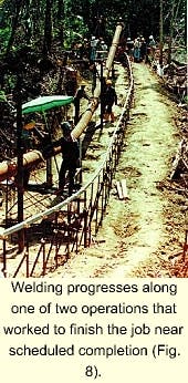
The welding process (Fig. 8) used inverter power source welding technology. These portable electric welding machines, powered by remote generators, were used instead of conventional heavy motorized welding "sets."
Generators were located along the ROW approximately every 1 km to keep power leads to a manageable length. As the welding front moved, welding machines were carried by monorack or hand and the generators moved by helicopter.
Over the first month, stringing, welding, helicopter support, and all areas of construction and logistics were examined and improved. The average welding progress increased from 60 to more than 100 m/day.
Even so, completion was going to be a year late at this rate, despite opening a second work front.
The second welding front heading into the rain forest near the well site 5 months after work began on the first front. The team capitalized on experience from the first front and made several improvements.
They formed dedicated stringing crews to keep the stringing several hundred meters ahead of the welders, changed the stringing equipment, and modified the pipe-hauling wagons. As a result, they were able to double the welding rate of the first crew.
These improvements were then transferred to the first front, where productivity also increased significantly.
Eventually, each of the crews was able regularly to achieve progress of 200 to 300 m/day.
Laying and welding for the last 20 km were completed in 55 days at an average rate of 360 m/day compared with a daily average of 86 m/day for the first 5 km. The highest single day record was 650 m/day for both fronts.
The flowline was constructed without tie-ins because it would have been very inefficient to move the welding crews back to a skipped location.
The flowline pipe was not rigidly attached to the H-frames. A modified floating design was used with the pipeline rigidly anchored every 500 m. Supports were placed on 12-m spacing and designed for 5,000-lb vertical loads and seismic Zone 4 conditions.
Anchors were designed for the same 5,000-lb vertical load as well as a 7,500-lb axial load.
Quality-assurance inspection
All welds were radiographically inspected. The x-ray labs were heli-portable and located at each camp.
Every day's welds were inspected; repairs and follow up x-ray were completed immediately. This procedure was necessary so that the welding crew would not move too far ahead and have to backtrack for repairs.
Welding rates were excellent under the conditions of constant high humidity, heavy rain, slippery footing, and at times deep mud: An overall weld reject rate of only 1.15% was achieved.
Cable tray
A heavy-gauge, galvanized steel cable tray was attached to the H-frame supports after pipeline installation.
The original design called for the cable tray to be mounted on the outside of the H-frames. After installing a few meters, however, it became obvious that the exposed cable tray could become a footpath, allowing unwanted access to the forest by outsiders.
The design was changed so that the cable tray was on the inside of the H-frame underneath the pipe (Fig. 9). This resulted in a more robust installation, partially protected by the pipe. A solid cover was riveted to the top of the cable tray. - The galvanized cable tray holds the 35-kv cable under the flowline (Fig. 9).
Power, fiberoptic cables
Electrical power reaches the well site through three single conductor power cables. Cable spools were 1,650 m long (the maximum weight of a reel that could be transported by helicopter) and installation was accomplished by hand pulling with rollers.
After the power cable was installed, a fiberoptic communications cable was placed in the same cable tray. This cable was comparatively easy to install because of its lighter weight and greater flexibility.
Fiberoptic cable spools were 6,500 m long. Production averaged about 200 m/day for the power cable and nearly 500 m/day for the fiberoptic cable.
Valve stations
Along the route, six remotely operated shutdown valves were installed.
This is a significantly higher number of valves than would normally be installed over this distance. The increased number was to limit environmental damage if a leak occurs.
Valve-actuator power is from local solar panels set on modified 40-ft cargo containers that house the valves, control panels, and batteries. Valves are monitored and controlled from the CPF through the fiberoptic cable.
Also included in the control scheme was a mass-balance pipeline leak-detection system.
Logistics
All materials, supplies, equipment, and people were flown in and out of flowline work areas by helicopter. The primary cargo carrier was a Boeing 234 Chinook capable of carrying loads up to 22,000 lb.
A Eurocopter 333J Puma was used to supply the daily requirements of the construction effort including food, water, and fuel; it also moved the welding generator sets.
A Bell 212 was the primary passenger mover. Helicopters were shared with other project activities requiring helicopter support, including drilling operations.
Despite frequent bad weather, which grounded the helicopters for days at a time, more than 37 million lb of materials and equipment and 24,000 passengers were safely flown for flowline construction.
In total, 3,968 joints of pipe, 221 km of cable, 9,475 piles, 76,000 pop rivets, 980,885 man-hr, and 33,770 meals were required for installation of this unique project.
Revegetation
The final construction step involved cleaning up all work areas and campsites along the flowline route. Topsoil and vegetation from the ROW and work locations were spread back over cleared land.
An independent company developed a reforestation plan addressing which plants should be used, how they were to be planted, and how to control soil erosion at each site.
Costs
The total cost for this 44-km flowline, including power and fiberoptic cable installation, was $27.3 million.
Subtracting the power and fiberoptic cable and 7 km of buried, conventional pipeline, the cost of installing 37 km of 12-in. OD, aboveground flowline appears in Table 1.
Even with the significant helicopter expenses, this pipeline installation technique is competitive with conventional construction techniques while achieving dramatically reduced environmental impact.
The Authors
Kenneth L. Lathrop has retired after 15 years with ARCO. He served as Villano facilities and pipelines project manager for ARCO Oriente Inc. and spent 30 years working as an engineer, contract administrator, and project professional. Lathrop holds a BS in electrical engineering from Kansas State University, Manhattan, and an MBA from Drake University, Des Moines, Iowa.
Robin W. Draper was Villano flowline project manager for Fluor Daniel Williams Bros., based in Quito, Ecuador. He is currently assigned to the Fluor offices in Sugar Land, Tex. Draper has been involved with fast-track, grassroots oil and gas construction project management in Ecuador for the last 8 years. Previous assignments have included facilities and pipeline construction and operations work in Venezuela, Indonesia, and Alaska. Draper holds a BS in metallurgical engineering from California Polytechnic State University, San Luis Obispo.
Christopher E. Slack is an independent project management and control consultant specializing in cost, schedule, special studies, and project analysis. For the Villano project, he worked for Fluor Daniel Williams Bros. in the project's engineering and construction department. Slack has worked in Asia and both North and South America. He holds a BS from Clemson University, Clemson, SC, and an MS in international trade and development from Penn State University, University Park.
