Gas-plant update moves Tengiz field toward 2004 producing target
Since acquiring Tengiz oil field in West Kazakhstan in 1993, the Tengizchevroil (TCO) partnership has undertaken several capital investment programs and expansions that have resulted in a steady rise in crude oil production to 9.6 million tonnes per year (tpy; 220,000 boed) in 1999 from 1.5 million tpy in 1993.
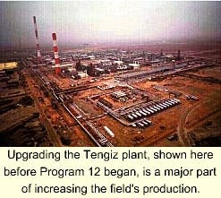
One such project, Program 12, is one of the current projects required to realize sustained production at 12 million tpy. The project will leave the Tengiz facility set for the next phases of expansion that will cost almost $3 billion over the next 4 years with production expected to reach 370,000 boed in 2004.
This article describes the LPG upgrade of $150 million Program 12.
Tengiz oil field
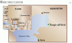
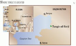
The Republic of Kazakhstan (Fig. 1) encompasses 2.7 million sq km, about four times the size of Texas or roughly equivalent to Western Europe. It is land locked at the heart of Central Asia.
The land is dominated by the vast flat grasslands of the Steppe, bordering in the west the Caspian Sea. The climate is arid with cold winters and hot summers.
Tengiz lies on the northeast Caspian shore at the western edge of the steppes and is subject therefore to temperature extremes, 44° C. (111° F.) summer to -40° C. (-40° F.) winter (Fig. 2).
The Tengiz oil field produced first oil in 1991. The production facility, originally implemented by the former Soviet Union (FSU), is a world-scale capital investment.
The TCO partnership is a joint venture of Chevron Overseas Co., (KazakhOil) National Oil & Gas Co., Mobil Oil Kazakhstan Ventures Inc., and LukArco Services BV. Oil production under TCO has grown steadily to 220,000 b/d from 24,000 b/d. Tengiz crude is a light high-quality product, with an 0.787 sp gr (48.2 API) and sulfur 0.49 wt % with light mercaptans 5 ppm.
The Tengiz oil field, discovered in 1979, is the largest discovered in the last 25 years. It has 3 billion tonnes (24 billion bbl) of oil in place with 6-9 billion bbl of estimated recoverable oil.
The reservoir also has significant associated gas reserves, 1,800 billion cu m (64 tcf). The reservoir is deep (target depth 4,500 m) and sour at 12.5 mol % H2S, with a relatively high temperature and pressure (flowing temperature 80° C., flowing pressure around 110 bar, shut-in pressure 550 bar).
Development of the remote Tengiz field, required a major effort to establish infrastructure.
While the majority of the infrastructure was designed and implemented by the Russian Technical Design Institutes, the process plant was built by a consortium of Western contractors (Lurgi/Litwin/Lav- alin).
Each building block or unit is called a "Complex Technology Line" (or "KTL," an acronym for its Russian language name). Each KTL consists of the following:
- Two trains of gas-oil separation, including oil-water separation and stabilization and sour-gas compression.
- Two trains of amine-based acid-gas removal.
- Two trains of Claus sulfur plant and tail-gas treating.
- One common gas-processing plant.
- One common on-plot utility block.
- One common control room.
It is the combination of acid-gas removal, sulfur recovery, high GOR, and rich associated gas that makes each KTL a substantial facility. Since 1993, when TCO was formed, a series of projects have been executed to improve and expand the infrastructure and production facilities.
As is common in oil and gas production facility design, significant flexibility was built in to allow for uncertainty in reservoir performance and reservoir composition.
Based on production experience from KTL-1 and KTL-2 and knowledge of the produced fluids, the first target for cost-effective capacity was debottlenecking. The projects executed in this period focused on increasing crude capacity and, consequently, production has outpaced the gas-processing capacity.
The next opportunity after debottlenecking was again to build on the existing asset and infrastructure, primarily the fact that the Claus sulfur plant capacity exceeds requirements because H2S levels are lower than originally designed for.
With the existing sulfur-plant capacity in four trains, there was sufficient margin to handle debottlenecked sour-gas flows plus the flow from a fifth crude oil production train.
The resultant Train 5 project includes a production train, new utilities, a plant-wide control room, and a gas-processing plant that can handle excess gas from KTL 1 and 2 in addition to Train 5.
With the commitment of these expansion projects, TCO will have a facility by mid-2000 capable of processing 12 million tpy of crude oil.
It was also recognized, however, that certain critical off-sites and utilities could not support this. And, that the infrastructure and long-term environmental performance required detailed assessment.
TCO was aware of the issues of constraint but needed to frame them into a project. This project is called Program 12.
CPDEP execution
As do other international exploration and production companies, TCO utilizes a structured approach to project planning and execution, known as Chevron Project Development and Execution Process (CPDEP), that has five phases (Table 1).
Each phase has three steps: work execution, deliverable production (either a plan or an asset), and management decision to proceed to next phase.
Stakeholder communication is an important part of successful project execution. To ensure correct decision making, the end users must approve the project at each hold point. Key stakeholder issues for TCO are the existing plant, language, logistics, regulatory impact, funding cycles, and the varying financial climate.
This latter point was particularly critical for the project because TCO's ability to fund capital projects depends heavily on crude oil revenue and hence the oil price. At the end of 1997 when the project started, the oil price was $18/bbl; by the end of 1998, this had fallen to $10/bbl. Yet, by mid-1999, it had recovered to $20/bbl.
Phase 1
In October 1997, TCO held workshops in Tengiz with the stakeholders to identify the key opportunities and requirements. This was documented, reviewed, and a strategy initiated for the work.
Fluor Daniel was approached to form an integrated team with TCO personnel for the project-framing stage that kicked off in February 1998. In parallel, Parsons Group International Ltd., London, initiated work on reviewing the existing four sulfur plants.
The Phase 1 report, issued in April 1998, detailed the scope areas for Phase 2 covering oil export, gas and LPG processing, sulfur plants, field facilities, and infrastructure.
For the purposes of this article, only the gas and LPG aspects of the project will be discussed. The project had the following objectives:
- Minimize or eliminate routine flaring by the end of Program 12.
- Maximize crude oil export volumes by butane blending, as economically justified.
- Maximize the net present value (NPV) of LPG.
- Provide an alternative disposal outlet for LPG.
Gas-plant configurations
As stated, by the time Train 5 is complete, Tengiz will have three gas plants, all with similar capacities. The original KTL gas plants are essentially identical.
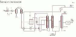
The original configuration was targeted for flexible production of sales gas, an ethane-rich petrochemical feedstock, CIS-grade propane, CIS-grade "broad fraction" (BF; a poorly fractionated blend of propane, butane, and some C5+), and debutanizer bottoms for recovery into the crude. (CIS = Commonwealth of Independent States, the loose federation that succeeded the FSU)
Since there are no local petrochemical plants, the de-ethanizer overhead is routed to sales gas, and the associated turbo expanders were never commissioned. The single depropanizer produces CIS propane with a side draw of BF for partial treating.
The product specifications for the CIS-grade LPG products are significantly less stringent than for European products. Consequently, the gas-plant facilities that are in place make products that TCO cannot sell on the world market. Fig. 3 illustrates the process scheme.
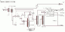
The Train 5 gas plant has a significantly different configuration (Fig. 4). The key points are that it has no demethanizer (no ethane product required) and has a depropanizer and debutanizer with propane and butane treaters to provide conventional propane and butane products.
Phase 2
During Phase 2, 14 options for gas and LPG processing were evaluated. At present, only a very limited market exists for both products, and in many circumstances TCO is reluctantly forced to flare these light hydrocarbons.
Five key strategic options were reviewed in detail:
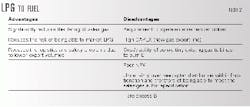
- LPG to fuel. The strategy here is to maximize the use of CIS LPG as fuel in Tengiz and inject propane into the sales gas up to the specification limit. Train 5 propane-butane would be exported. Table 2 shows the advantages and disadvantages of this option.
- LPG to market. This option (summarized in Table 3) recovers the propane and butane as conventional products by revamping the KTL gas plants and LPG storage and export facilities and using sales gas as fuel in Tengiz.
Typically, LPG volumes on this scale (131 tonne/hr) would be moved by pipeline or ship or barge. Since Tengiz is land locked and constrained to LPG export by rail, logistics are a key consideration.
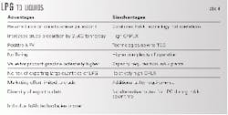
- LPG to liquids. This option (Table 4) converts all LPG to liquid products, which can be blended into crude oil or sold as gasoline blend stock. Sales gas is used as fuel in Tengiz.
Three suitable LPG-conversion technologies were identified.
- 1. Cyclar (BP-UOP) converts LPG into benzene, toluene, and xylene that may be blended with the crude stream or exported as aromatics.
- 2. InAlk (UOP) dehydrogenates the C3 and C4 material and polymerizes these olefins to C6 to C8 material that may be blended with the crude or exported as gasoline blend stock.
- 3. Fischer-Tropsch (SASOL-type process) converts the LPG (and natural gas) to paraffin for export with the crude.
For the unique Tengiz situation, the InAlk technology provided the best fit for LPG conversion.
- LPG to injection. This option (Table 5) uses Train 5 butane as fuel in Train 5 and reinjects all other LPG into a nearby oil reservoir. Injection into the Tengiz reservoir was rejected because of the very high pressure required and lack of proven pumping technology.
- LPG incineration. This option again uses Train 5 butane as fuel, then burns all excess LPG in purpose-built ground flares (Table 6).
Moving ahead
With strategy options reviewed, including technical and financial cases for each, a recommendation was needed for management and partner approval. Table 7 summarizes LPG production and disposition for each case including a base case, or "do nothing" case.
Financial modeling was developed to determine the NPV of each case. This was then fed into a decision risk analysis, including a series of sensitivity analyses.
LPG to market was recommended and approved. The option was chosen because it:
- Provides a significant NPV for the LPG product.
- Minimizes flaring.
- Provides opportunity to slip some butane into the crude up to the vapor pressure limit if economically justified.
- Can be implemented in stages to provide significant flare reduction in the short term, realize LPG revenue, satisfy budget and cash flow constraints, and prove up the market prior to full investment.
Phase 2 of this project lasted from May until November 1998.
Phase 3
As mentioned, a feature of the LPG-to-market strategy is the ability to stage the work to meet TCO's cash flow objectives yet achieve early increases in LPG export.
The implementation plan is phased over three stages. The Stage 1 scope is to:
- Install a propane treater and drier in KTL-1, which will also treat propane from KTL-2 (note lower flow rates prior to fractionation modifications).
- Upgrade the LPG storage and rail loading facilities.
- Install a sweet-gas crossover system from KTL-1 and KTL-2 to load the Train 5 gas plant.
This stage gives a fast track to facilitate export of Train 5 LPG products, maximize Train 5 gas plant utilization, and export a substantial quantity of the existing KTL propane. It leads to a significant reduction in flaring coincident with Train 5 start-up.
Stages 2 and 3 install full LPG fractionation, complete LPG treating, and install sour-gas cooling and condensate-stripper reboiler upgrades, first in KTL-1 and then KTL-2.
Program 12 has a CAPEX budget exceeding $300 million, more than half of which is for the LPG upgrade.
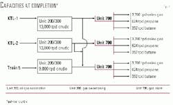
Fig. 5 summarizes the status of the process-unit capacities after Program 12.
Due to the level of study and definition performed in Phase 3 and the fast-track nature of the Stage 1 work for the propane treater, stakeholder approval was managed so that approval of the strategy and funding for Stage 1 was achieved by December 1998.
This was critical so that the treater package could be delivered to site (which for skids of this size is only viable by ship or barge) before the weather window closed in autumn 1999.
If transportation were delayed until the Volga-Don canal opened in spring 2000, start-up to coincide with Train 5 would be in jeopardy.
Phase 3 culminated with approval for funding of this full scope in June 1999. The aggressive schedule for the Stage 1 treater was achieved with the placing of the modules on the foundations in December 1999.
In addition to front-end engineering and design, Phase 3 included many studies to address issues raised during Phase 2, which did not affect the overall strategy.
Following is a discussion on three significant technical issues.
LPG treater
With the move to market LPG to Western specifications, the LPG treating for sulfur removal had to be addressed. The comparative sulfur specifications for the CIS and Western products are: CIS propane, H2S and mercaptan sulfur-130 ppm (wt); CIS BF, H2S and mercaptan sulfur-250 ppm (wt), H2S-30 ppm (wt); in contrast, Western propane and butane: H2S-0.5 ppm (vol), H2S + COS-1 ppm (wt), total sulfur-15 ppm (wt).
The Tengiz reservoir with its high H2S content is also characterized by a high level of organic sulfur species: heavy mercaptans, light mercaptans (RSH), and COS.
This presents two significant challenges: predicting the distribution within the process plant and their removal by different processes. The heavy mercaptans predominantly stay with the crude oil and are not such a safety or environmental concern as the light (predominantly methyl and ethyl) mercaptans.
Prediction of the disposition of the light mercaptans and COS within the process train due to physical processes (cooling, flashing, distillation) and absorption processes (amine DEA) is difficult. TCO has undertaken extensive field laboratory analysis and correlation against process simulation and thermodynamic packages.
Similarly, the removal efficiencies using DEA in the main amine sweetening process have been reviewed. The results of this work have been fed back into the simulation models to provide the best pragmatic fit.
The light mercaptans and COS demonstrate limited absorption in the gas sweetening amine unit, and work their way through predominantly into the LPG products. The light mercaptans must also be limited in the sales gas; this and the Wobbe number specification dictated the demethanizer and de-ethanizer operating conditions.
This drives the sulfur species into the LPG. Therefore, a robust solution for LPG sweetening is required.
Light mercaptans will be present in both propane and butane but can be removed readily using Merox-type technology with a sponge-oil system to remove disulfide oil. Removal of small quantities of H2S in a caustic-based treater is not an issue. But the COS is known to migrate into the propane stream.
Removal of the COS is the most significant technical challenge. COS can be removed with selected amines by staged contacting devices. Tengiz treater designs are constrained by the desire to use the site amine, DEA. Not the optimum amine for this application, DEA is nevertheless the typical amine used in refinery applications.
DEA is used at site currently for removal of COS from BF in a mixer and settler system. The efficiency of the stages, however, is relatively poor, and the specification of 1 ppm H2S + COS is far from achievable.
Consequently, a key consideration is the stage efficiency of the contactor device. Several existing LPG treaters operate at site with varying success.
The Train 5 project, proceeding ahead of Program 12, had already placed orders for COS and mercaptan treaters from Merichem Chemicals and Refinery Services, Houston. This scope consisted of:
- Propane: Two-stage DEA Aminex and single-stage caustic treater.
- Butane: Two-stage caustic treater and a common caustic regeneration unit.
Program 12 has a clear requirement for LPG treating, but evaluation was required to formulate a strategy and confirm that the COS-removal technology works.
The following options were considered: install, modify, or revamp existing equipment; procure and install Train 5 copies.
Given the status of existing equipment, it was clear that additional LPG-treating capacity would be required in any case. In recognition of the staged execution strategy, a propane COS/RSH treater was needed on a fast-track basis.
For several reasons, including equipment commonality, a repeat order was placed with Merichem for a Train 5-type propane treater and caustic regeneration unit to be installed in KTL-1. A propane drier repeat order was also placed.
The technical risk of achieving the COS specifications was reviewed in detail by Merichem, Chevron specialists, and Fluor Daniel technical experts. The Merichem Aminex process uses a two-stage countercurrent design with co-current Fiber Film technology to provide the contact area and residence time.
Although there were no reference units for this technology in operation using DEA, Merichem has worked closely with Chevron, initially at a refinery and subsequently in laboratory trials.
The key to performance is the ability of DEA to absorb COS and the stage efficiency of the Fiber Film contactor. Merichem expects the exit COS to be 0.5 ppm and guarantees 1 ppm. The feed temperature of 54° C. is critical. After close review, we were able technically to support the expected performance and remove this as an issue.
The clear commercial and technical solution was to remove the existing treaters and install duplicate Train 5 units in both KTL-1 and 2.
LPG storage, loading
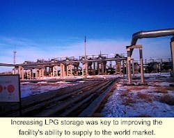
Tengiz has an existing LPG storage and rail-loading facility. For the LPG-to-market strategy, this facility is key. The Tengiz LPG export operation will be world scale, considering the volumes to be loaded and rail car movements.
The existing facilities consist of a remote bullet park with 40 bullets and 4 pumps of varying capacities. The rail-loading rack is all manual with 60 railcar loading slots representing the capacity of a single train.
Although the storage and loading capacity is adequate for limited export, the existing facilities are not configured appropriately and do not satisfy the safety and operational requirements of TCO, especially considering the substantial increase in throughput.
In parallel with review of revamp options, new facilities based on spheres and semi-automated railcar loading systems were reviewed. The existing facilities were surveyed by an external peer group of LPG-handling specialists, and a strategy for an economically viable revamp was put forward.
This supported the desire to continue to utilize the existing bullets and rail-loading rack, which are fit for purpose. Various upgrade strategies were reviewed with a fit-for-purpose discrete event analysis tool.
Critical parameters for review included setting a strategy for sampling and laboratory analysis of the product before generation of an export passport and determining the optimum loading rates and loading system flexibility against storage volume and manpower requirements to support varying marketing requirements.
The stakeholders reviewed the strategies and approved the selected strategy: 20 revamped bullets, with a further 10 identified for future revamp, and all 60 loading slots available.
As has been recognized earlier, the logistics of the operation reliably to load and transport of 96 rail tank cars (RTCs) a day is a major challenge. TCO will have upwards of 5,000 RTCs on long-term hire to support this operation. Peripheral operations such as RTC movement tracking, cleaning, and maintenance also become a major factor.
The scope of the revamp is summarized as follows:
- Three additional rail car sidings.
- Fire protection upgrade including detection, fire fighting. and firewater impoundment.
- Replacement of some stairs and platforms.
- Reconfigure relief valve headers.
- Cleaning and upgrade of 20 bullets, 13 propane, 7 butane.
- Remove fuel-gas blanketing to prevent product contamination and provide nitrogen for purging.
- Off-spec rerun system to plant.
- Pairing of bullets, bullet-level instrumentation, and ESD /switching isolation.
*New loading-pump suction headers, ESD valves and canned loading pumps, 350 cu m/hr propane, 175 cu m/hr butane.
- Storage park and plant data link, ESD and control systems.
- Conversion of loading spots to incorporate new valving, 10 propane, 30 propane+ blend , 20 butane+ blend.
- LPG blender and composite samplers for all three products.
Data capture
A critical need of design engineers when working on brownfield projects has been to have ready access to accurate data for the existing plant. Without this, retrofits and plant modifications cannot be efficiently executed.
Although this need has remained constant over the years, what has varied is the capability of technology and industry to acquire the data. This capability has grown from simple use by field-based designers of rulers and sketchpads to the application of more advanced technologies such as photogrammetry and laser scanning that enable plant data to be captured without the need physically to measure.
Fluor Daniel has significant experience in application of both techniques, and the project evaluated available survey methods in order to select the most fit-for-purpose solution. Key factors in this evaluation included:
- Lack of existing drawings.
- High cost of placing designers in the field.
- Requirement to minimize physical contact with live plant due to safety considerations.
- Schedule drivers requiring fast acquisition of data.
- Physical size of plant areas, for example, requiring more than 7,000 photographs for photogrammetry.
- Extreme environmental conditions for surveying (temperatures typically in the high 40s° C., sandstorms, and large daily diurnal changes being recorded).
- Inaccessibility of some areas of process plant would have resulted in inaccuracy if physically measured.
Laser scanning techniques have evolved so that they are economically viable for data capture on process plants. The project has evaluated UK Robotics, which has developed a laser scanning system that captures more than 11 million data points in a 2-min scan, thus overcoming many of the time and cost issues associated with plant data capture.
This data-capture mechanism is supported by software which enables the user to view the data in either a 3D "photobrowser" (giving the ability to take desktop measurements from the scanned images with an accuracy of 6 mm) or an engineering 3D CAD model. Thus, the information can be represented in the format is most appropriate to the project.
Given the challenges of the location, it was crucial to be able to view and analyze the collected data at site immediately after collection. The modeling software enabled this to be carried out on completion of each 2-min scan and highlighted any deficiencies.
It would clearly be unacceptable to realize a problem existed with the captured data after the surveyors had returned to the UK.
The project would have taken a significant amount of time and been very labor-intensive if either manual data capture or photogrammetry had been used. With laser scanning and close liaison with the client's team in Tengiz, the data was captured within 5 weeks.
A total of 80 gb of data were recorded, which clearly offered significant time and cost benefits to the project. In addition, the data captured were downloaded to CD and viewed back in the UK offices much more quickly than would have been possible with more standard technology. This was extremely important to the project because early engineering decisions could be taken from measurements made using the 3D photobrowser.
The Authors
Dave Connell is the engineering and procurement manager on Program 12. Previously, he was engineering manager on the Train 5 expansion project for the Tengiz field. He has worked for Chevron since 1977 in various engineering and project assignments. He holds a BS in chemical engineering from the University of Arizona.
Connell served as chairman of the European Chapter of the GPA in 1998 and has been a member of the management committee for the past 7 years.
Bob Ormiston retired in March 2000 after 33 years with Chevron. For the majority of that time, he held various process-engineering positions and most recently was in project management. He was one of the earliest Chevron employees to be assigned to Tengiz, leading the on-site process engineering team and finally as project engineer on Program 12. Ormiston holds a BSc in applied chemistry from Glasgow University and a PhD in chemical engineering from Cambridge University.
Nick Amott is a senior manager, process engineering with Fluor Daniel in the UK. He has been with the company for 19 years, holding various process engineering positions. Previously, he worked for Lummus for 4 years. Amott holds a BSc (1978) in chemical engineering from the University of Surrey and is a Fellow of the Institution of Chemical Engineers.
Irene Cullum, lead process engineer for Program 12, worked with Fluor Daniel since 1990. Previously, she worked for Kaldair and Sasol. Cullum holds a BSc (1980) in chemical engineering from the University of the Witwatersrand, South Africa, and an MASc in chemical engineering from the University of Toronto.
Based on a presentation to 79th Annual GPA Convention, Mar. 13-15, 2000, Atlanta.
