Fast-tracked FCC revamp meets project goals
Williams Refining LLC, a division of Williams Energy Services, successfully implemented a major revamp to increase the capacity and yield of its fluid catalytic cracking unit (FCCU) in Memphis, Tenn.
The project was accomplished in less than 1 calendar year, from start of engineering to completion of the turnaround. It was completed on time and on budget, and it performed according to guarantees.
International Alliance Group (IAG), Houston, was the general contractor for project management, procurement, engineering, and construction. The FCCU revamp used technology from UOP LLC, Des Plaines, Ill.
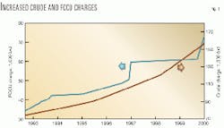
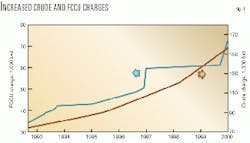
The Memphis refinery currently processes 150,000 b/sd of crude oil, up from 40,000 b/d in the late 1980s. Fig. 1 shows the FCCU and crude throughputs during the past 7 years (OGJ, Mar. 22, 1999, p. 58).
Revamp needs
In 1998, Williams Refining LLC purchased the Mapco Inc. Tennessee refinery. Williams' vision for the refinery through 2001 included plans for a crude-unit expansion, a new continuous catalytic reformer, and FCCU and alkyation unit capacity increases.
The county approved the prevention of significant deterioration (PSD) permit for these projects in July 1999. The new FCCU flue-gas scrubber significantly reduced environmental permitting issues.
By mid-1998, the timing for the 1999 turnaround had been established, but the FCC project was still undefined. The FCCU turnaround needed to address several issues:
- The FCCU was operating at rates 40% above the 1995 design, therefore pushing unit limits.
- Regenerator cyclone inlet velocities in the regenerator were 110-120 fps.
- Catalyst standpipe fluxes had reached 1.25 million lb/hr/sq ft.
- The reactor had excessive catalyst losses, about 4-6 tons/day.
- The regenerator combustor was approaching 8 fps superficial velocity.
- Coke-burning operations were leaving 0.15 wt % carbon on the regenerated catalyst.
With the FCCU revamp, the company wanted to increase the unit's feed rate capability to 69,000 b/d. Williams also wanted the revamp to allow for processing a lower-quality feedstock. The gravity of the new feedstock would be 2-4° API lower, and the Conradson carbon residue was expected to increase from 1.8 to 2.2 wt %.
Time was tight. It was September of 1998, and the refinery turnaround was scheduled to begin in 14 months. The timing of the turnaround was not negotiable. Any schedule changes would have had a negative impact on cost and downtime, and an opportunity to take advantage of certain market demands would have been missed.
Williams targeted a 21-25 day window for the refinery turnaround. This timing considered market-supply requirements, refinery economics, and refinery intermediate and product storage capabilities.
Key to FCCU revamp
Williams contacted two FCC technology licensors to conduct revamp feasibility studies. The studies analyzed the best technical options and weighed their benefits vs. cost, implementation, and constructability. The licensors started their feasibility studies in September 1998.
At one point, the licensors entertained the idea of completely replacing the conversion and catalyst section of the FCCU. The analysis showed, however, that a new unit had three major disadvantages: The costs were prohibitive, the plot space was nonexistent, and a new FCC catalyst and conversion section could not be completed in time to meet the turnaround window.
The revamp option was the only realistic alternative.
Williams ultimately selected UOP to provide the FCC technology for this revamp. The key technology that allowed Williams to address many of its objectives within the turnaround window was the use of UOP's Vortex Separation System (VSS) inside the regenerator.
Although UOP's VSS is well proven as a reactor riser-termination device, this would be the first regenerator VSS installation to be put into service.
The VSS essentially replaces the first-stage cyclones, creating room for larger single-stage cyclones. Larger cyclone diameters and a larger inlet area allow for handling of the expected higher flue-gas rates as a result of increased crude oil throughput and operating severity.
Use of the VSS in the regenerator meant that both the 15-ft reactor and 24-ft regenerator diameters could be maintained, minimizing the structural revisions. This solution reduced the plot-space requirements, turnaround duration, and was more cost effective than the other options reviewed.
In addition to the upper regenerator VSS, UOP also proposed a larger diameter combustor section efficiently to carry out the carbon burn of the spent catalyst. The larger diameter combustor could be fit into the structure.
On the reactor, UOP proposed additional revisions including elevated Optimix feed distributors, a larger and longer riser for increased residence time, new reactor cyclones, and a new spent catalyst stripper employing UOP's latest high-efficiency tray design.
The revamp also included larger catalyst standpipes, expansion joints, and slide valves. In essence, the entire catalyst section of the plant would be replaced and tied into the existing reactor vapor line and flue-gas ducting. Fig. 2 shows a sectional elevation of this proposed layout.
In addition to these changes, the FCCU main fractionator and gas-concentration system would require modifications to handle the increased throughput and provide for improved fractionation and recovery.
Outside help
As the feasibility studies and planning sessions progressed, Williams no longer had the resources available in-house.
The company invited International Alliance Group (IAG) of Houston and others to submit proposals and execution plans to implement the proposed FCCU revamp. Williams selected IAG based on its experience in turnaround and project management and its track record.
IAG delivers technology for refinery revamps, defines and establishes real economic opportunities, provides single-point responsibility with turnkey pricing for technology, and executes projects supplying project management, engineering, procurement, and construction.
IAG's involvement began by assisting with final technology selection and economic justification analysis. IAG analyzed the numerous revamp options being proposed by both licensors and assessed the economics, constructability, and schedule of each option within Williams' prescribed constraints.
These constraints included cost-effective retention of existing structure, turnaround start date, turnaround completion date, and capital limitations.
Williams and IAG combined their collective experiences to choose a detailed engineering firm, primary contractor, equipment vendors, and field subcontractors. Williams and IAG created a "Dream Team," composed of many members with long track records in FCCU turnaround specialties and familiarity with the Memphis refinery.
Among others, team members included Altair Strickland Inc., Deer Park, Tex., for FCCU-structure construction, MPEC Inc., Houston, for process engineering of the main column and gas-concentration system, Stewart & Bottomley Inc., Tulsa, for detailed engineering, and UOP for basic engineering and process technology licensing.
Williams relied on IAG to manage relationships among the team, which allowed Williams to concentrate on the overall effort and to focus on areas that needed special emphasis.
Project goals, justification
The ongoing feasibility study and economic analyses provided the ability clearly to identify realistic goals for the revamp of the FCC. Specifically, the goals for the revamp included:
- Increasing capacity of the unit to 69,000 b/sd with a future capability of 75,000 b/sd.
- Reducing reactor catalyst losses from 4-6 tons/day to fewer than 1.5 tons /day.
- Improving conversion and gasoline yield by 3.5 liquid vol %.
- Providing the capability for future heavier feed operation.
- Reducing the regenerator-cyclone inlet velocity.
- Improving catalyst circulation and regeneration capability.
- Expanding the capacity and recovery in the main column and gas-concentration system.
- Meeting the scheduled turnaround start date and duration.
Meeting the scheduled turnaround date required a solid project scope that would not change significantly. A solid scope was necessary to start the basic engineering, define long lead items, and secure early funding for the basic and detailed engineering and purchase of the long lead-time equipment.
Final funding approval occurred in late February 1999. Until the end of February, Williams issued purchase orders to IAG with cancellation charges for the licensor, engineers, and contractor to assist in project justification and scope development in the event the project was not fully funded.
Based on UOP's final design basis and yields, Williams and IAG prepared a detailed project justification for approval. This justification required estimating the downstream-unit effects, expected revenues, equipment costs, implementation time, and the erected cost. This effort took 2 months and was completed in January 1999.
Long-lead fabricated equipment identified during project justification was pre-funded with purchase orders containing cancellation charges. The list included:
- Reactor (stripper) with VSS and UOP's new high-efficiency stripper tray design.
- Regenerator and combustor with VSS.
- Cyclones for the reactor and regenerator.
- Wet-gas compressor components.
- Slide valves.
- Expansion joints.
- Riser, standpipe, and UOP Optimix feed distributors.
The reactor and regenerator vessels, with their associated internals, governed the implementation schedule.
Project scope
The extensive economic analysis and project justification phase allowed Williams and IAG to define a complete scope of work for the revamp.
MPEC used UOP's yield analysis for preliminary process design of the main column and gas-concentration sections. Stewart & Bottomley followed with preliminary mechanical design for the downstream requirements. Altair Strickland assisted in constructability reviews and provided detailed construction pricing.
The "final" project scope could not be altered significantly if the turnaround schedule was to be met. The "final" scope for the revamp included the long-lead fabricated equipment already identified in addition to the following:
- New catalyst standpipes including a second catalyst recirculation line.
- Orifice-chamber modifications.
- New power cabling for the main air blower.
- Main column internal upgrades.
- Sultzer and UOP VGMD trays in the primary absorber, stripper, and debutanizer columns.
- New feed-piping system, exchangers, and controls.
- Slurry and light cycle oil heat integration system upgrades.
- Various exchanger, pump, piping and instrument control system enhancements.
The final capital project scope, economically justified and submitted for approval, was about $35 million.
Project implementation
As mentioned earlier, prefunding for the basic engineering, detail engineering, and long lead-time equipment items started well before final approval. Although this work strategy would result in recycle and could potentially result in higher costs, it was the only way Williams could meet its aggressive turnaround schedule.
UOP began basic engineering during the economic analysis and project justification phase of the project.
This was approximately 10 weeks before Williams provided official approval for this project. The feasibility study and initial feedback from the economic analysis phase allowed Williams to identify major design items.
The justification phase of the project called for replacement of the reactor and the regenerator combustor and head. This option was more cost effective than retrofitting and reusing pieces.
The diameter of these new vessels would have to be the same as the existing vessels to retain the existing structure. This information allowed UOP to start the basic engineering even though the rest of the scope and processing objectives had not been finalized.
UOP forwarded its preliminary basic design to Stewart & Bottomley for preliminary detailed engineering for these vessels. Stewart & Bottomley's preliminary detailed design was sufficient for IAG to prepare bid packages and select fabricators. It also allowed IAG to place firm orders for the reactor on Jan. 13, 1999, and for the regenerator on Jan. 28, 1999.
This overlap of basic and detailed engineering was the only way to meet the scheduled turnaround date. The concept was extended to remaining equipment for engineering, procurement, and construction to meet an established turnaround date of Oct. 18, 1999.
By the time the raw material arrived at the fabricator's shop, the scope and processing objectives had been finalized. UOP and Stewart & Bottomley began to finalize the engineering specifications and design for this equipment based on the final project scope.
Under IAG's direction and supervision, all equipment fabrication, delivery, and inspection were rigorously staffed and expedited. The interwoven requirements of engineering and procurement provided very little or no float time for the major equipment. These tight and highly dependent deadlines meant sometimes revising designs and fabrication to meet the schedule.
With the help of IAG, Williams integrated the schedule and contractor requirements for maintenance work with capital work. Maintenance work scopes were budgeted at approximately $10 million and included work outside of the FCCU.
In numerous instances, the contractors adjusted work activities and sequences to keep the project on or ahead of schedule with little or no cost impact. The capital work was executed primarily on a lump-sum basis with the remainder on a guaranteed maximum. There were change orders, but all were within the contingencies established during the project justification phase.
Over the 10-month implementation phase, weekly meetings were held via video conferencing. These meetings served as an open channel of communication, updating all parties on schedules, costs, upcoming week's requirements, and milestones.
Scope changes were held to a minimum and in every case the scope adjustments were justified by economic payout, operability, reliability, and safety. The emphasis by all team members was on maintaining schedule and overall project cost.
In mid-April 1999, UOP completed its basic engineering specifications. Williams and IAG established a final qualified sub-contractor bid list in June. A short unit outage in early June verified that the replacement of the regenerator shell was cost effective because of the condition of the refractory.
Even at this stage of the project, flexibility in accomplishing the goals overrode earlier decisions. IAG prepared and issued sub-contractor bid packages based on preliminary designs in June. IAG selected and awarded final contracts through August.
Stewart & Bottomley continued with detailed design engineering into September 1999. Procurement of long lead-time equipment and specialty items and valves continued through August. Expediting of material, inspections, and quality control was ongoing until the shipment of the last long lead-time item.
A detailed preturnaround and turnaround construction schedule allowed six 10-hour days for preturnaround work and two 12-hour shifts working 7 days/week for the turnaround. IAG initiated the preturnaround work in July and completed it on Oct. 17, 1999, when the FCCU was shutdown.
The actual turnaround mechanical work started on Oct. 18, 1999, and was completed by Nov. 11, 1999. Oil was introduced to the FCCU late that evening, culminating a 25 day "oil out to oil in" turnaround.
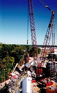
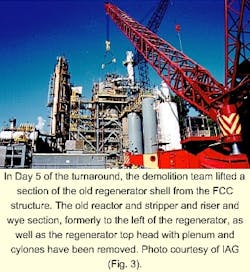
Figs. 3 and 4 show construction photos of removal of part of the regenerator and installation of the new stripper section of the reactor.
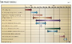
Capital construction work associated with insulation, instrumentation, and miscellaneous structural and clean-up continued until Dec. 15, 1999. Fig. 5 shows the FCCU project implementation schedule. In Day 7 of the turnaround, cranes lifted the new stripper section of the reactor, which contained the internal riser and UOP VSS riser-termination device, into place. Photo courtesy of IAG (Fig. 4).
In the end, the revamp project scope was constant with the exception of the new regenerator shell and replacement of an existing catalyst slide valve. Both affected the critical path and were cost effective scope revisions.
Revamp results
The start-up of the revamped unit began with oil introduction on Nov. 11, 1999, meeting the project goal. The start-up of the unit was smooth and absent of the catalyst carryover that had plagued this unit during the past several years. Within 2 days of oil introduction, the unit was processing 68,000 b/sd, essentially the proposed design capacity.
Despite subsequent power failures and externally induced upsets to the FCCU, the unit has experienced no catalyst losses and easy unit restart. After working through an inventory of heavier-than-design feedstock contaminated with high sodium, calcium, and iron concentrations, the unit performed well, exceeding proposed goals and design criteria.
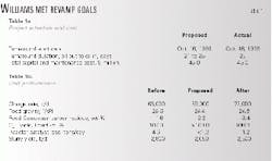
Table 1 summarizes the major goals of the revamp alongside of its actual performance. The major goals have been met. As these goals formed the basis of the economic justification, meeting and exceeding of these goals ensure the profitability of the revamp.
The Authors
William G. Miller is president of Williams Refining LLC in Memphis and Williams Olefins in Geismar, La. He is also a vice-president of the Williams Cos., Tulsa. He joined Mapco Petroleum in 1993 as vice-president of refining, leading both the Memphis and Alaska refineries. Miller previously was the executive vice-president of El Paso Refining. He holds a BS in chemical engineering from Iowa State University, Ames.
Jeffrey K. Warmann is the operations manager for Williams Refining LLC in Memphis. He was project and turnaround manager for this recent FCC revamp. He has had various management and engineering positions with Mapco Petroleum, Process Services Inc., Edeco Inc., Warmann Oil Co., and Fina Oil & Chemical Co. Warmann holds a BS in chemical and petroleum refining engineering from the Colorado School of Mines, Golden, and an MBA from the University of Missouri, St. Louis.
Alan D. Copeland is manager of process engineering for Williams Refining LLC in Memphis. He was chief process engineer on this recent FCC revamp. Copeland has previously held various positions with Mapco Petroleum, Delta Refining Co., and Earth Resources. He holds a BS in chemical engineering from the Christian Bros. University in Memphis.
Terry L. Stewart is a vice-president for International Alliance Group in Houston. He has responsibilities in project development, management, and engineering. He was project director of the recent FCC revamp. Prior to joining IAG in 1998, Stewart was a co-owner and president of Stewart & Bottomley Inc. He holds a BS in chemical engineering from Oklahoma State University, Stillwater.
