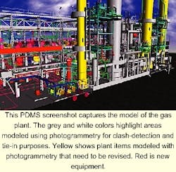
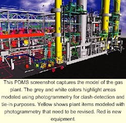
Refinery revamp uses photogrammetry to produce as-built model
Having used three-dimensional (3D) computer aided design (CAD) technology on numerous greenfield engineering projects, Kvaerner Engineering & Construction, Zoetermere, The Netherlands, successfully used it on a complex brownfield situation.
The 3D CAD technology reduced the number of rework items during the engineering-drawing stages of a revamp of Royal Dutch/Shell's Pernis, The Netherlands, refinery by 95%.
Accurate as-built information for oil and gas facilities is often difficult or impossible to obtain. This exact problem confronted Kvaerner process engineers when they began a major maintenance and refurbishment project for the fluid catalytic cracking unit (FCCU) No. 2 and unsaturated gas plant No. 3 units at the Pernis refinery.
Although such 3D technology has radically transformed the design and fabrication of new oil and gas facilities in recent years, few applications have been found in plant maintenance and refurbishment projects.
Close-range photogrammetry
Having used 3D CAD technology on numerous greenfield engineering projects, Kvaerner was eager to employ CAD technology on the Pernis project, which was a brownfield situation.
As-built plant drawings are the traditional starting point for generating a 3D CAD model. The whereabouts and existence of the as-built plant records for the involved Pernis refinery units, however, were uncertain.
Kvaerner needed a method to transfer the current plant configuration quickly into an electronic file. The electronic drawing needed not only to reflect the as-built configuration of the plant, but also to encompass the numerous modifications made during the life of the facility.
Kvaerner chose a technique called "close-range photogrammetry" to generate a model of the two refinery units to be revamped.
The process plant industry first applied photogrammetry in a "close-range" situation in the 1980s. The combination of photogrammetry and 3D CAD modeling is an accurate and cost-effective means by which technology-literate companies can achieve monetary savings and reduce project durations.
The photogrammetry technique heavily depends on complete photographic coverage of a plant to generate a 3D model. This does not differ from other technologies such as laser mapping. After acquiring photographs of the plant, photogrammetry can then produce a plant model with an accuracy of plus or minus 2-5 mm.
The on-site practical execution of a close-range photogrammetric survey involves the placement of control targets around a plant. Surveyors then survey and record the coordinates of these targets using highly accurate theodolites, optical surveying instruments.
Photographers shoot the plant from different angles to ensure complete coverage. Photographs using 65-mm film are taken with a Bronica camera with a specially modified glass backplate.
The photogrammetry software uses control targets visible in the photographs as known reference points, from which any other position in the photograph can be measured. By digitizing plant items captured in the photographs, plant designers can create a complete model of the facility reflecting plant configurations at the time of the survey.
Although Kvaerner was an early adopter of photogrammetric technology in the mid-1990s, it later found that subcontracting this type of work to companies such as Survey-2-CAD, which specialize in close-range photogrammetry and 3D-CAD modeling, was more cost-effective.
Kvaerner thus contracted Survey-2-CAD to produce a full PDMS (plant-design management system) model of the existing FCCU2 and gas plant No. 3 units at the Pernis facility. Three Survey-2-CAD teams, each consisting of a surveyor and photographer, captured in excess of 2,000 pairs of images of the plant.
The teams used these images to produce a 3D PDMS model for Kvaerner. The model represented the as-is status of about 50,000 cu m of intricately arranged process piping, equipment, structural steel, and concrete.
In all, the team surveyed and modeled three areas of the refinery to a tolerance set by the client at plus or minus 10 mm. Survey-2-CAD delivered the model to Kvaerner 12 weeks after the completion of the site survey.
Scope of work
Kvaerner used the model supplied by Survey-2-CAD for revamps of the FCCU2 and gas plant units at the Shell Pernis site. The model served as a multidisciplined design tool to optimize design coordination; safety, maintenance, operational, and construction input; and internal and client reviews.
The complexity of the revamp and the short scheduled shutdown period of 4.5 months made photogrammetry the only logical solution to meet the requirements of the project.
With a lack of "as-built" information and a tight time schedule, the photogrammetry option required less intervention, provided a head-start on the schedule, and allowed early identification of potential clashes. This technique had rarely been applied to a brownfield project, however, let alone one of this size and complexity.
Shell and Kvaerner defined the level of detail early in the project definition phase; this time is generally when the contractor determines how detailed the survey needs to be, in relation to the client's needs.
The scope of the work was then decided-upon by Kvaerner together with Survey-2-CAD. The 2,000 photos were shot within 16 days. It took 2 weeks for Survey-2-CAD to process the photo data to produce and deliver a visual database of the images to Kvaerner.
Challenges
Choosing to undertake photogrammetric surveys presents its own challenges in comparison with more-traditional survey methods.
Accuracy is critical during the acquisition of the photogrammetric data. Any discrepancies in the data taken for at the Pernis refinery could have resulted in false clash reports.
The environment within the plant is also critical. The presence of plumes of steam within a plant could interfere with the accurate logging of information during the survey because the measurements are based on the recording of visual information. Interference with data collection could in turn affect the schedule. Luckily, in this case, there was little atmospheric interference.
A particularly important aspect in using photogrammetry is the early identification of insulation on existing pipelines. True pipe-size cannot be read from the photo because the photogrammetric survey provides volumetric information only.
Therefore, any insulation must be opened up accurately to gauge the dimensions of the underlying equipment. Support from the client is crucial in finding true pipe sizes. Contractors should allocate time in planning schedules to allow for collecting this information.
Using photogrammetry for modeling existing equipment requires human involvement. Although the photogrammetric model identified items such as valves, flanges, and nozzles with the correct dimensions and ratings, there was still remaining work for Kvaerner's designers.
The designers had to trace or recheck the relevant parts of the model to produce isometric drawings detailing the parts of the plant to be demolished. This job involved extra manhours for entering and checking data.
Despite these complications, use of photogrammetry in this particular case produced results that satisfied expectations all round. The use of a model reduced the number of field reworks items by more than 95%. Survey-2-CAD subsequently produced a PDMS model from photogrammetry which was used by Kvaerner to successfully complete a project on a different unit in the same refinery. F
The authors-
Iain Fraser is director of Survey -2- CAD Ltd., Bury, Lancashire, UK. During the last 4 years, he has been part of a team of three technical directors responsible the production and delivery of 3D photogrammetric models. Previously, he worked for Kvaerner Surveys for 3 years as an engineer and project manager. Fraser holds a BSc (honors) in construction design and management from the University of Northumbria at Newcastle, Newcastle Upon-Tyne, UK.
John van der Vliet is piping supervisor for Kvaerner Process (Netherlands) BV, Zoetermeer. He is responsible for progress administration, technical performance, new developments, design ergonomics, budgets, and assignment of technical and human resources to to projects.
Van der Vliet has over 35 years' experience in piping design for petrochemical plants and oil and gas installations worldwide.


