Application of new code will extend equipment lives
Prudent use of the American Petroleum Institute's Recommended Practice (RP) on fitness-for-service (FFS), API RP 579, will allow plant owners to make better repair and replacement decisions.
This article presents an overview of FFS technology, examples illustrating the use of this technology in day-to-day plant operations, and a summary of the future changes required to existing in-service inspection codes to facilitate the use of this technology.
The American Petroleum Institute (API) released RP 579 for determining FFS of pressure vessels and piping in early 2000. This document provides guidance for determining when repairs or replacement of equipment is necessary. It is a large and highly detailed industry consensus work, representing years of effort on the parts of many owner-users and industry consultants.
What is FFS?
The ASME (American Society of Mechanical Engineers) and API design codes for pressurized equipment do not address in-service equipment degradation nor deficiencies in original fabrication.
These codes currently do not permit crack-like flaws, have empirical rules used for acceptance of metal loss, and provide minimum guidance on the acceptability of other flaws and damage types (for example, blisters, creep, and fire damage). As a result, operators often bring units down to repair or replace equipment incorrectly or unnecessarily.
An FFS assessment is an engineering analysis of equipment to determine whether it is fit for continued service. The equipment may contain flaws, may not meet current design standards, or may be subject to more severe operating conditions than the design conditions.
The product of an FFS assessment is a decision to operate the equipment as is, or to alter, repair, monitor, or replace the equipment. RP 579 also provides guidance on appropriate inspection intervals.
FFS assessments use analytical methods to assess flaws and damage. They require an interdisciplinary approach with operations personnel consisting of an understanding of
- Damage mechanisms and material behavior.
- Past and future operating conditions.
- Nondestructive examination techniques (flaw location and sizing).
- Material properties (environmental effects).
- Stress analysis (finite element analysis; FEA).
- Data analysis (engineering reliability models).
Use of FFS can extend the useful life of aging equipment. In some cases, it allows new equipment with flaws to enter service without repairs. Operating companies realize significant savings because FFS enables the operator to operate equipment until the next scheduled downtime without compromising safety.
The use of FFS often results in the avoidance of repair or replacement in situations in which the conventional codes would have required expensive solutions.
API RP 579
RP 579 provides guidance for conducting FFS assessments using methods specifically prepared for equipment in the refining and petrochemical industry. The guidelines can be used to make run-repair-replace decisions to ensure that pressurized equipment containing flaws can continue to operate safely.
RP 579 supplements the requirements in API 510 (pressure vessel inspection code), API 570 (piping inspection code), and API 653 (aboveground storage tank inspection code). The new API recommended practice has three functions:
- To ensure safety of plant personnel and the public while older equipment continues to operate.
- To provide technically sound FFS assessment procedures to ensure that different service providers furnish consistent life predictions.
- To help optimize maintenance and operation of existing facilities to maintain availability of older plants and enhance long-term economic viability.
The driving force behind the development of RP 579 is plant safety. The methods described in RP 579, together with the appropriate API inspection code, can be used to show compliance with US OSHA 1910 PSM (Occupational Safety & Health Administration 1910 Process Safety Management) legislation.
The assessment procedures in RP 579 can be used for FFS assessments and for rerating of components designed and constructed to the following codes:
- ASME Boiler & Pressure Vessel (B&PV) code, Section VIII, Division 1.
- ASME B&PV code, Section VIII, Division 2.
- ASME B&PV code, Section I.
- ASME B31.3 Piping code.
- ASME B31.1 Piping code.
- API 650.
- API 620.
They can also be used for pressure-containing equipment constructed to other recognized codes and standards, including international and internal corporate standards.
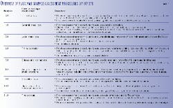
Table 1 is an overview of the flaw and damage-assessment procedures covered in RP 579.
If an FFS assessment indicates that the damaged equipment is suitable for the current operating conditions, the equipment can continue to be operated at these conditions provided suitable monitoring and inspection programs are established.
If the FFS assessment indicates that the damaged equipment is unsuitable for the current operating conditions, the recommended practice provides calculation methods to rerate the component.
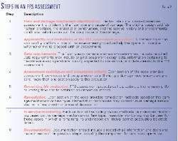
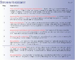
Table 2 lists the procedures to conduct an RP 579 FFS assessment for all flaws.
RP 579 provides three levels of assessment for each flaw and damage type. In general, each assessment level provides a balance among conservatism, the amount of information required for the evaluation, the skill of the personnel performing the assessment, and the complexity of analysis being performed.
Level 1 is the most conservative, but it is easiest to use. Practitioners usually proceed sequentially from a Level 1 to a Level 3 analysis (unless otherwise directed by the assessment techniques) if the lower level assessment does not provide an acceptable result or a clear course of action.
- Level 1. The assessment procedures included in Level 1 provide conservative screening criteria. These require a minimum amount of inspection or component information. Level 1 assessments may be performed by plant inspection or engineering personnel.
- Level 2. The assessment procedures included in Level 2 provide a more detailed evaluation than in Level 2. The results are more precise (that is, less conservative) than those from a Level 1 assessment.
A Level 2 assessment requires inspection information similar to that for a Level 1 assessment. The Level 2 evaluation uses more detailed calculations, however. Plant engineers or engineering specialists experienced in performing FFS assessments typically conduct Level 2 assessments.
- Level 3. Compared to Levels 1 and 2, a Level 3 assessment requires the most detailed evaluation. The results are more precise than those from a Level 2 assessment.
A Level 3 assessment typically requires the most detailed inspection and component information. The recommended analysis is based on numerical techniques, such as FEA.
A Level 3 analysis is primarily intended for use by engineering specialists experienced in performing FFS assessments.
Examples
Case studies showing the benefits of FFS technology are described in the following assessment examples. In all cases, significant savings resulted from a decrease in maintenance costs and a minimization of operational downtime.
- Cracked ring-joint flange. A hydrogen processing vessel had cracks in the ring-groove radius region of a ring-joint flange. The operator conducted an FFS assessment based on an FEA.
The analysis and fracture-mechanics concepts indicated that the driving force for crack propagation was high for a very localized region near the ring groove radius. Crack propagation decreased significantly, however, for deeper cracks.
The assessment also showed that the highest stresses occurred during the bolt-up operation. The chemistry, grain size, microstructure, and hardness of the material indicated that the material had good resistance to hydrogen-assisted crack growth during downtimes and to crack advances during service.
Based on the results of the FFS, the engineering and inspection team recommended that starting up the unit without repair of flange cracks. The plant realized a substantial cost savings from avoidance of repairs and extension of the shutdown duration.
* Severe out-of-roundness of a new pressure vessel. During field erection in a petrochemical plant, one company accidentally dropped a new pressure vessel. The vessel's shell distorted in excess of ASME code limits.
The operator used an FFS assessment to evaluate the integrity of the distorted shell under internal pressure loading. Engineers constructed a finite-element model of the distorted geometry based on field measurements. The assessment included an evaluation of the collapse strength under internal pressure loading as well as a fatigue assessment.
The results of the FFS assessment indicated that the vessel shell was acceptable for future operation at the original design conditions. The use of FFS technology eliminated the need for costly repairs to the new vessel as well as significant costs associated with unplanned operational interruption.
- Pitting in a sludge tank. In one refinery, operators and inspectors found numerous through-wall pits in a sludge tank. The pits (about 1-in. diameter) were forming in the lower course of the tank where the fiberglass-reinforced plastic lining was damaged. In one area, four pits were within several inches of each other.
The refinery performed an FFS assessment to evaluate the pitting damage to develop a fill height restriction. The FFS assessment indicated that a restriction on the liquid fill height was not required based on the current size and density of pits.
The plant also used the results from the FFS assessment to develop limits on pit size and spacing so that it could determine when future repair would be necessary. In this case, the savings resulted from not having to rent additional tankage.
- Fire-damaged vessel. A major fire in a refinery resulted in excessive distortion of the shell of a vacuum tower. Using field measurements of the distorted shell profile, the refinery performed an FFS assessment to evaluate the structural integrity of the damaged shell.
The assessment indicated that the integrity of the vessel had not been compromised. This evaluation eliminated the need for costly repairs and avoided an extension of the unplanned shutdown, resulting in savings of more than $500,000.
- Caustic tank with an internal partition plate. An internal partition plate in a 40-ft diameter caustic-storage tank permitted operational flexibility without the need for a second small tank. After 3 years of service, the frequent fill cycling of the tank produced a fatigue failure. Inspectors found through-wall cracks at the location of external stiffener welds.
The nature of the stored product made the situation intolerable. Operators performed an FFS assessment to evaluate the original design to determine whether the problem was related to the design or was caused by environmental cracking.
The FFS assessment showed that the original design was inadequate from a fatigue-stress standpoint. The plant analyzed several design-modification options, and developed an optimal repair plan based on cost and time out-of-service.
The repaired tank provided the operational flexibility desired, while eliminating the concern of future fatigue failure. There was no need to add storage, and reliability and availability were improved.
* Settlement of aboveground storage tanks. Many old aboveground storage tanks rest on inadequately designed foundations. The result is shell and local bottom settlement in excess of that permitted by API 653 Appendix B.
Engineers have performed FFS assessments using techniques based on nonlinear FEA on tanks of various sizes. The results of these assessments show that settlement-related repairs to the tank bottom were not necessary 90% of the time.
Settlement repairs are very costly if done correctly, often requiring a tank lift that can cost between $100,000 and $500,000, depending on the size of the tank. Additionally, tanks must be out-of-service for substantial lengths of time to perform these repairs, resulting in high business interruption costs.
FFS assessments can significantly reduce the need for these expensive repairs. For example, one owner who annually took 10-15 tanks out-of-service for maintenance, has saved an average of $300,000/year by avoiding unnecessary tank-settlement repairs.
- Creep life assessment of a refinery pressure vessel. One refinery conducted an FFS assessment to evaluate a fluid-catalytic cracking reactor vessel that had operated in the creep range for almost 45 years. An initial damage assessment based on elastic stress analysis indicated that the vessel was approaching its predicted failure life. Thus, there was little potential for increasing the operating temperatures.
In this situation, engineers performed an FFS assessment that included material testing of vessel samples and using nonlinear FEA to re-evaluate the vessel. The assessment indicated that operation at increased temperatures was feasible for a projected time of 20 years. The owner saved about $4 million associated with process improvements and the avoidance of vessel replacement.
- Redesign of partition plates and internals in a refinery process tower. A refinery tower with an internal partition plate and tray arrangement developed cracks in some of the tray-support members.
Engineers used FFS assessment techniques to design modifications to the vessel's internals that would improve the reliability of the tower. They used FEA to determine the stress distribution in the original tower internals. The FEA showed that the vertical partition plate deformed excessively under the pressure gradient acting on the tray and on the partition itself.
Engineers used results from the FEA to evaluate several design modifications. The addition of a vertical gusset on the backside of the partition plate was the most effective repair. The modification eliminated the likelihood for future cracking of the tray supports.
The new design not only improved the vessel's reliability, but also eliminated the potential for an eventual through-wall crack, which would have had serious safety implications.
Changes to API codes
The release of RP 579 will bring about some changes to other existing API codes and recommended practices. The long-range plan is to offer an integrated suite of API codes and recommended practices, where information is presented once and the other documents refer and are linked to that information.
The in-service inspection codes in the US for refining and petrochemical pressure-containing equipment are
- API 510 for pressure vessels.
- API 570 for piping.
- API 653 for tankage.
- ANSI NB-23 (National Boiler Inspection Code) for pressure vessels & piping.
Until very recently, these codes imposed an inspection interval based on equipment condition with a maximum inspection interval based on corrosion rates. API 510, 570, and 653 have been revised to allow the use of risk-based inspection methodologies as an alternative to established inspection intervals. This is a fundamental change in these codes.
The current plan is to revise API 510, API 570, and API 653 to permit the use of RP 579 for FFS assessments. When these revisions are complete, several fundamental changes will be represented in the codes:
- Crack-like flaws may be acceptable in all of these codes.
- Metal loss will be evaluated using technology-based rules.
- Better guidance on assessment procedures for common types of damage mechanisms found in the refining and petrochemical industry will be provided.
There is also a plan to produce a primer booklet about RP 579 for inspectors. The booklet would include relevant sections from RP 579 that deal with data needs and Level 1 assessment procedures. It would contain only limited discussion on remaining life and monitoring issues. This booklet will then serve as an additional study guide for the API inspector-certification exams.
While extremely valuable, as demonstrated in the earlier examples, RP 579 is a complex, comprehensive document. As a service to the user community and to ensure rapid use and understanding by the industry, API is conducting several RP 579 training courses in the US and overseas.
The author-
David A. Osage is a principal mechanical engineer with M&M Engineering. He is responsible for engineering consulting services for pressure containing systems. He is also chairman of the API RP 579 Fitness for Service Committee. Osage has more than 20 years' experience in the refining and petrochemical industry.
Formerly, Osage was an owner-user engineer with Exxon and BP Oil. He holds bachelors and masters degrees in mechanical engineering from Stevens Institute of Technology, Hoboken, NJ. He is also a registered professional engineer in Ohio.


