Acid-gas injection proves economic for West Texas gas plant
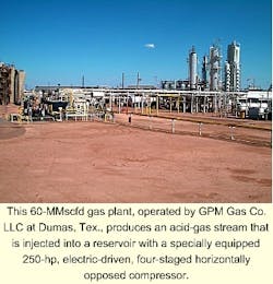
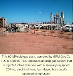
GPM Gas Co. LLC, formerly GPM Gas Corp., realized significant cost reductions with an acid-gas injection well at its 60-MMscfd Dumas, Tex., gas plant.
The company chose the injection scheme when faced with the increasing regulatory requirements and higher operating costs associated with sulfur-recovery units.
After securing approval from the Texas Railroad Commission (RRC) pursuant to Statewide Rule 36(c)(10), GPM drilled and completed an acid-gas injection well to a total depth of 5,600 ft. Before injecting into the Granite Wash formation, the company completed reservoir and concrete compatibility studies to ensure operability.
The processing plant produces a 450,000 scfd acid-gas stream consisting of 27% H2S, 71.5% CO2, and 1.5% C1. The acid-gas stream is injected into the reservoir with a specially equipped 250-hp electric-driven four-staged horizontally opposed compressor.
Granite Wash formation
With the increase of sour-gas production, processing industries are realizing the limitations of both grandfathered acid-gas flaring permits and high operating costs associated with standard sulfur recovery units.
To combat these obstacles, GPM pursued the alternative solution of an acid-gas injection to address both capacity and cost issues at the Dumas plant, which is in Moore County, Tex., approximately 45 miles north of Amarillo.
A majority of the gas production in the Texas Panhandle is from the Brown Dolomite formation at 3,133-437 ft deep. The Granite Wash formation at 4,562-932 ft, however, is typically used for produced water and Class I hazardous-waste injection in this region because of its elevated porosity and shell-like structure. The thick and porous formation characteristics allow it to accept large quantities of disposal fluids.
Before re-injection of the produced acid-gas stream from the gas-processing plant's amine treater, approval from the RRC pursuant to Statewide Rule 36(c) (10) was required. In addition to complying with all Rule 36 requirements, GPM completed reservoir compatibility and sensitivity assessments for the Granite Wash formation.
A specially equipped 250-hp compressor compressed the 450,000 scfd acid-gas stream consisting of 27% H2S, 71.5% CO2, and 1.5% C1 from a 5 psig suction to a 615-psig discharge for re-injection into the formation. As with any acid-gas mixture, the company gave special consideration to mitigating corrosion and hydrate-formation problems.
Regulations
The RRC, under Statewide Rule 36, requires that a processing plant producing a 100-ppm H2S radius of exposure greater than 50 ft from the H2S source must meet, but is not limited to, the following requirements:
- Establish adequate warning and marking provisions.
- Maintain adequate security provisions.
- Construct all relevant equipment and piping with metals that resist hydrogen sulfide stress cracking.
- Install additional control and equipment safety provisions, if required by Rule 36 (c) (7).
- Maintain a written contingency plan in the event of an H2S release.
- Maintain protective breathing equipment in two or more locations.
- Install wind direction indicators at strategic locations.
- Install automatic H2S detection and alarm equipment.
- Provide H2S training to all employees and contractors.
- Notify RRC district office of any accidental release.
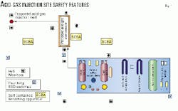
In compliance with Rule 36 and company safety policies, the area surrounding the injection site is equipped with several safety devices including H2S detectors, windsocks, self-contained breathing apparatus, and remote unit and plant shutdown stations.
Fig. 1 shows the location of these safety devices.
In addition to these requirements, commission approval following a public hearing is required before an injection of any fluids containing H2S.
The Granite Wash is a sweet formation by nature, which caused the commission to raise concerns about injecting acid gas into the sweet zone as opposed to re-injecting directly into the naturally sour Brown Dolomite formation.
To address these concerns, the company conducted a study of offsetting wells in a 2-mile radius from the proposed acid-gas injection site. The study identified eight active wells drilled to the Brown Dolomite formation.
Only one reported active well, approximately 6.5 miles away, was drilled in the Granite Wash and Moore County Lime formation. Since the Granite Wash formation is nonproductive in this field, injecting the acid gas into the Granite Wash formation significantly reduced the liability of re-exposure through existing well bores.
In addition, the high porosity and water saturation characteristics of the Granite Wash significantly reduces the migration rate of the acid gas in the Granite Wash compared to the Brown Dolomite.
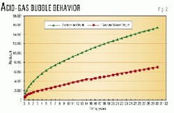
As seen in Fig. 2, the acid gas in the Granite Wash formation will migrate only 1 mile from the well bore over 20 years. The same acid-gas stream, however, would migrate approximately 2.5 miles in the Brown Dolomite formation over the same period.
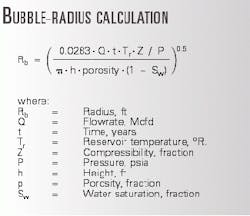
The equation in the accompanying box calculates the bubble radius in feet.1
The commission created a special field designation "Gr. Wash-H2S Displ" to designate the acid-gas injection zone. With all these factors considered, the commission approved injection of the Dumas plant's produced acid-gas stream into the Granite Wash formation.
Testing, design
Several preliminary tests were conducted by Hycal Energy Research Laboratories Ltd., Calgary, using previously attained drill cuttings from the Granite Wash formation, to ensure structural compatibility with the proposed acid-gas mixture.
Hycal conducted both petrology studies and reservoir quality and sensitivity assessment studies on drill cuttings from the prospective formation.
The laboratory reported that the rocks of the Granite Wash underlie a thick (1,100-ft) section of Moore County Lime that contains light grey to medium grey, calcite cemented, skeletal lime grainstones to packstones with low effective porosity and very low permeability. The cuttings indicated low permeability in the 0.01-0.05 md range.
The overlying Moore County Limestone would bar any acid gas from migrating up the formation and exposing existing wells drilled in the Brown Dolomite formation.
In addition, the petrology indicated the sandstone in the Granite Wash formation had sufficient permeability and storage capacity for the acid-gas injection rates proposed. Analysis indicated the permeability in the Granite Wash formation rocks in the 300-500 md range.
Hycal determined the Granite Wash was a good candidate for the acid-gas mixture. Analysis indicated, however, that a trace amount of bitumen was in the formation. Although unlikely, it was possible that the bitumen may not be compatible with acid gas and could lead to a sludge or emulsion formation.
Along with the independent laboratory studies, the company evaluated the injection volume from a nearby plugged Granite Wash disposal well against the proposed acid-gas injection volume for comparison.
The proposed acid-gas injection rate was one-tenth of the continuous rate previously accepted by the disposal well over a 4-year period. From all accounts, the Granite Wash formation appeared to be a very suitable zone for acid-gas injection.
Concrete compatibility testing with the acid-gas stream was also conducted before the injection well was drilled. Three types of concrete blocks were weighed and installed in the acid-gas stream for several weeks: a noncarbonate and calcium blend, a resin-based cement blend, and a 50/50 Pozmix with latex blend.
The first cement blend shattered and was therefore unacceptable. The other types showed little to no weight reduction and were therefore acceptable options for cementing requirements. Based on cost, GPM chose the 50/50 Pozmix with latex blend.
The casing program for the acid-gas injection well consisted of the following phases:
- 133/8 in. 48 lb H-40 to 800 ft.
- 95/8 in. 36 lb J-55 to 2,250 ft.
- 7 in. 26 lb J-55 to 3,800 ft.
- 41/2 in. 11.6 lb J-55 to 5,500 ft.
The injection tubing consisted of 23/8 in. 4.7-lb L-80, internally plastic coated pipe with injection perforations located between 4,600 and 5,500 ft. To protect the annulus between the tubing and casing, a 1% amine-based inhibitor was premixed with a 2% KCl fluid and pumped into the annulus.
To detect a tubing or casing leak, the annulus pressure is monitored for high or low pressure. In the event of a detected leak, the unit is automatically shutdown and isolated at both the compressor and the wellhead.
Surface equipment, design
The water-saturated acid-gas stream leaves the amine-regeneration skid at approximately 5-10 psig and therefore must be compressed to meet the reservoir pressure for re-injection established at 615 psig.
A 250-hp motor equipped with a variable-frequency drive (VFD) drives the four-stage horizontally opposed compressor to complete the compression cycle. The compressor and all piping and vessels were built to NACE Standard MR-01-75 and API RP 14E standards.
As previously mentioned, addressing corrosion issues received special consideration.
To reduce the corrosion severity of the acid-gas system, the acid gas should contain less than 2 bbl water/1 Mscf gas. Based on obtaining free-water knockout at the discharge scrubber, the water ratio of the water saturated acid gas was calculated at 0.25 bbl/1 Mscf. The low water-to-gas ratio predicated a low corrosion rate of 1.25 mils/year (mpy).
Therefore, carbon-steel construction was used along with installation of suction and discharge scrubbers equipped with mist eliminators. For protection of the discharge piping and the injection tubing, however, an amine-based chemical inhibitor is injected downstream of the discharge scrubber.
The compressor is equipped with separate crankcase and cylinder lube-oil systems. The crankcase uses a typical petroleum-based 30-40 weight oil blend. The compressor cylinders, however, use a specially blended poly-alkaline glycol oil mixture that resists the corrosive environment of the acid gas.
The compressor is also equipped with a two-compartment distance piece with a modified packing case to accept an external purge 10-15 psi more than the primary packing and vent drain pressure. The continuous sweet gas or nitrogen purge forces any compressed gas leaks through the packing case to the primary packing vent and drain system, thus preventing any corrosive acid gas from entering the crankcase.
All vents on the acid-gas compressor system vent to a flare. Additionally, the compressor has the capability of compressing either sweet gas or nitrogen for purging procedures. An H2S analyzer is installed on the discharge line to aid in predicting when the unit is adequately purged.
The compressor skid is equipped with four independent H2S monitors on each corner of the compressor skid. Each monitor alarms at 10 ppm and 100 ppm. The unit is automatically shutdown on the 100-ppm alarm and signals the plant-evacuation alarm.
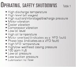
Upon an automatic shutdown, the suction-control valve, the discharge emergency-shutdown (ESD) valve, and the wellhead ESD all close, thus isolating the unit. The acid gas is then automatically diverted to the flare. Table 1 lists the unit's additional safety shutdowns.
Operating design, problems
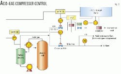
The acid-gas stream generated from the amine still is sent to the acid-gas compressor through a backpressure control valve set at approximately 10 psig. After four stages of compression, the acid gas is disposed back into the reservoir at a surface discharge pressure of 615 psig.
The acid-gas compressor is setup to operate from a backpressure control standpoint of the amine stills. The suction control valve to the compressor and the VFD to the motor are controlled by a split-range controller receiving a pressure signal from the reflux accumulator.
The first range (4-12 ma) operates the suction-control valve, while the latter range (12-20 ma) operates the VFD on the motor. Therefore, the suction-control valve will open accordingly to maintain 10-psig backpressure on the reflux accumulator.
Once the suction-control valve is fully open, the VFD on the motor will speed up or slow down to maintain the proper backpressure on the reflux accumulator. Fig. 3 illustrates the control scheme.
Should the backpressure to the accumulator increase to 13 psig, the excess acid gas is diverted to the plant flare for disposal. Should the backpressure continue to rise to 15 psig, the excess acid gas is then diverted to the plant's vent system.
As illustrated in Fig. 3, the flow recordings and analyzer data are captured in the supervisory control and data acquisition (SCADA) historian for accurate reporting of all disposed components. The commission requires this annual documentation.
The controllers are set up to be in automatic for start-up or shutdown. If the compressor shuts down, the Mod 30 will ramp up the setpoint to 100% to close the suction-control valve and take the VFD to minimum speed. During start-up, the Mod 30 setpoint will ramp down to a setpoint of 12 psig. This will allow the VFD to come up to minimum speed before opening the suction-control valve.
One major problem with acid gas is its tendency to form hydrates at relatively warm temperatures. The ability of CO2 and H2S to hold more water than hydrocarbons leads to the warm hydrate temperatures. However, H2S tends to dominate the hydrate formation temperature.
Therefore, it is important to maintain tight specs for the composition, temperature, and pressure of each stage of compression to prevent hydrate formation. It is also important to realize that a small amount of methane in the acid-gas stream will lower the ability of CO2 to hold water and will ultimately shift the hydrate temperature.
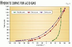
To ensure that no hydrates form, the acid-gas compressor temperatures are operated to remain above the hydrate and dew point curves. A hydrate curve was produced for an acid-gas stream of 27% H2S, 71.5% CO2, and 1.5% C1 (Fig. 4).
As shown, the acid-gas temperature throughout the stages of compression must be maintained greater than 75° F. to prevent hydrate formation.
The acid-gas compressor is sensitive to the carryover of any hydrocarbon and amine degradation products from the amine treater. On occasion, the amine-based products and hydrocarbons would carryover to the compressor and plug the compressor cooler or mist eliminators.
Hydro-blasting the tubes successfully cleared the cooler. To address these occasional problems, additional filtration has been installed on the lean and rich amine streams.
The unit has operated successfully with carbon steel compressor valves. However, the carbon steel floats in each scrubber did not withstand the corrosive conditions. The floats were replaced with stainless steel floats resulting in a much higher operating consistency.
The acid-gas injection project has proven to be a success at GPM's Dumas plant. The well has shown no signs of formation incompatibility to the acid-gas injection rates established. The unit has required little maintenance and operational attention.
Significant annual savings were realized using the acid-gas injection scheme as opposed to continuing a third-party processing agreement. The project was completed with economics supporting a 2-year payout.
Acknowledgments
Thanks are due Jim Bennett, Jim Fodor, and Mike Woodworth, all of North America E&P, Phillips Petroleum, for their valuable insight and guidance. This article is dedicated in memory of my father, Carl Gene Bennett, for his constant inspiration and guidance.
Reference
- Ikoku, Chi U., Natural Gas Reservoir Engineering, pp. 330-333 (Florida, Krieger Publishing Co.).
the author
Laurie Whatley is a process project engineer for Duke Energy Field Services Corp., based in Borger, Tex. In 1995, she was employed by GPM Gas Crio., biw oart if Duke Energy Field Services. She holds a BS (1995) in chemical engineering frim Texas A&M University.
