Paleomagnetism provides alternative core orientation methods
Paleomagnetic techniques provide a means for orienting the vast volumes of inventoried core samples. This article presents three methods, developed at the University of Windsor's Paleomagnetics Laboratory, for using the characteristic remanent magnetization in core orientation.
Oriented cores furnish geologists with useful data in oil and gas exploration and development, providing information on fracture orientation, anisotropy of permeability, variations in seismic velocity, and in situ stress tensors.
Conventionally, cores can be oriented during drilling by the conventional scribe technique or by matching formation micro-image (FMI) log features with the core.
Unfortunately, most core material in storage remains unoriented, as there are few methods available to obtain this information. Paleomagnetism-the study of the Earth's magnetic field variations through time-provides such a method.1-3
Paleomagnetic theory
Paleomagnetic measurements indicate the direction of the Earth's field as recorded in a rock sample. The magnetization direction has two angles relative to the Earth's surface: the declination angle, measured from north in the horizontal plane; and the inclination angle, measured from horizontal in the vertical plane. The declination of the present Earth's magnetic field can be measured with a compass.
In most rocks, the magnetic remanence, or the magnetization imprint carried within the rock properties (rather than induced by the Earth's magnetic field), is multivectorial. When a rock is formed, the magnetic vectors are aligned in all the magnetic grains.
If the rock experiences a subsequent overwhelming remagnetization event, then the vectors will be reoriented to the new Earth's magnetic field direction. If the remagnetization event is less strong, however, only some grains will be remagnetized. Thus, the sample will show indications of all events.
A magnetometer measures the total vector or the sum of all magnetizations. To discriminate between magnetic vectors, investigators expose samples, in steps, to increasingly elevated and alternating fields or temperature changes. Thus, grains with lower resistance levels of demagnetization lose their magnetization first.
At some point, the record of the initial magnetic direction is completely removed and the second (usually older) record then appears. This can be thought of as the "last in, first out" rule. The higher the field (temperature) to which each vector persists, the higher its coercivity (blocking temperature) and the greater its age.
The vector components, or magnetic directions, contained within a single specimen can be obtained with principal component analysis adapted for paleomagnetism. Components are usually defined with at least three demagnetization steps and have maximum angular-deviation angles of <13°.4
The mean direction for a specific component, carried by several specimens, provides the basic paleomagnetic information used on core orientation. Because the components represent vectors in space, spherical statistics are used to calculate their means and confidence limits.5
Methods
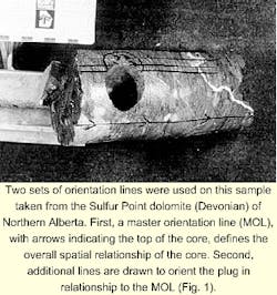
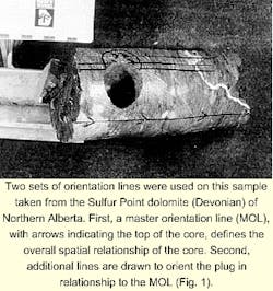
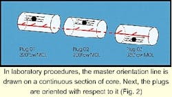
Each core sample is reassembled into continuous segments that are as long as possible. An arbitrary master orientation line (MOL) is drawn along the length of each segment. Next, 2.5-cm OD plugs are drilled perpendicularly to the core axis with azimuths measured clockwise relative to the MOL, looking down the core (Figs. 1 and 2).
The MOL serves two purposes:
- It provides a common reference line for all specimens within a segment, allowing direct comparison of their paleomagnetic data.
- It serves as the orientation marker for paleomagnetic methods-that is, the MOL for each segment is the line that is finally oriented in 3D space. When data processing starts, the MOL is assumed to be oriented at 0° (north) with a vertical core.
Statistically, the minimum number of specimen directions required to orient a segment is about 10.6 In practice, however, this number should be doubled, as experience shows up to 50% of the specimens are unusable. If a plug yields only one specimen, 15-20 plugs will then be required; if a plug yields two or three specimens, the required number of plugs decreases accordingly.
Before analysis, the specimens are stored in a magnetically shielded room with a field intensity of << 1% of the Earth's magnetic field intensity. This environment allows the least-stable laboratory magnetization components to decay while minimizing the possibility of spurious magnetization acquisition.
The natural remanence magnetization of each specimen is then measured on a Canadian Thin Films cryogenic magnetometer (CTF-420) at the University of Windsor, where representative specimens totaling about 10% of the collection are selected as pilot specimens.
These are subjected to either alternating fields of demagnetization in about 25 steps (ranging from 2 to 140 milliTesla using a Sapphire Instruments SI-4 alternating field demagnetizer) or in about thermal 30 steps (ranging from 80° to 580° C. using a Magnetic Measurements MMTD1 TH demagnetizer).
Core orientation
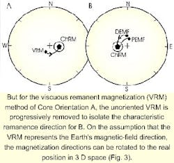
In the standard paleomagnetic technique for core orientation, investigators identify the low temperature or coercivity viscous remanent magnetization (VRM) during the stepwise demagnetization process.1 2 This component probably results from the core sitting in a relatively constant magnetic field of the Earth for the past million or so years and should be directed downwards in the northern hemisphere.
The mean direction of a core segment's VRM is then aligned to either the present Earth's magnetic field or the dipole-averaged Earth's magnetic field using the well's orientation as the rotational axis (Fig. 3).7
Once the amount of rotation between the initial direction and the true direction of the VRM is known, the MOL can be rotated to its true position in space, giving the true orientation of the core.
The VRM method, however, can be complicated by several factors. If a drilling-induced remanent magnetization event is present, the blocking temperature and coercivity ranges for the drilling-induced remanent magnetization and the VRM will overlap, making it difficult to isolate the VRM needed for core orientation.
Additionally, several examples of reservoir rocks in the Northern Hemisphere have been found where the low temperature and coercivity component is oriented upwards. This component is not a VRM and is unusable for orientation purposes.
In six studies from the Western Canada Sedimentary Basin, the VRM technique was wholly successful in only one, partially successful in three, and wholly unsuccessful in two reservoirs.8
ChRM methods
Most cores retain a higher temperature and coercivity characteristic remanent magnetization (ChRM), even in cases in which the VRM is degraded or absent. Most previous work on core orientation has ignored this magnetization component.
Where the VRM method proves unusable, however, the ChRM can often be used to orient the core. The methods are not exclusive: both the ChRM and VRM methods can be used to double-check and enhance the orientation resolution.
In fields where at least three wells are sampled that deviate in drilled directions by more than 10° from each other, their core magnetization angles can be used for orientation purposes. The core magnetization angle is the angle between the specimen's magnetization and the borehole axis, which is the same as the complement of the measured remanence inclination.
Since the core magnetization angle is unaffected by core rotations, the inclination-only mean is used to calculate this angle for each well. The core magnetization angle is plotted on a stereonet, forming a small circle about the orientation of the well itself.
The true magnetization orientation must lie on the circle (Fig. 4, A). For two wells, two small-circle intersections or two possible ChRM directions are present (Fig. 4, B); and for three wells, a unique solution exists (Fig. 4, C).
Once the true ChRM has been determined, individual rotations can be calculated for each well core segment and their MOLs rotated to orient the core. The oriented magnetization can be dated by comparison to the reference apparent polar wander path (see below).
Sometimes two wells may be used rather than three; for example, if one of the two intersection solutions provides a clearly valid answer and the other solution is nonsensical. It should be noted that this method is limited both by the availability of deviated wells and by the necessity for the ChRMs of each well to have the same age.
Paleopoles and APWP
The measured declination and inclination of the mean ChRM of a segment, collected at a known latitude and longitude, can be used to calculate the position of its magnetic north pole or paleopole.6 9 When the paleopole does not coincide with the present north pole, "apparent polar wander" becomes evident.
In reality, continental drift has caused the sampling site to shift, creating a difference or translocation distance between the paleopole and the present North Pole. Diagramming the site motion on the Earth's surface through time can be problematic or awkward, however.
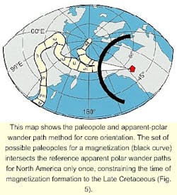
As a plotting alternative, paleomagnetists have created reference apparent polar wander paths (APWPs) for each continent that show the apparent position of its north magnetic pole through time (Fig. 5).10 Thus, comparing a collection's ChRM's calculated paleopole to the APWP makes it possible to date ChRM formation.
In the studies, the ChRM inclination, site latitude, and site longitude are known; the declination is the only missing variable. Using all possible values for the declination (0° to 360°), a set of possible paleopoles can be generated that form an arc on the Earth's surface (Fig. 5).
The arc's intersection with the reference APWP must pinpoint the real paleopole and define both the time of magnetization and its true declination. Knowing the true declination, the orientation of the MOL can be corrected and the orientation of the core determined.
This method can be complicated by two factors:
- If a structural tilt occurred after the ChRM was acquired, then the paleolatitude will be affected and must be tilt-corrected before applying this method
- A unique solution may not be present if the arc intersects the APWP more than once.
Remagnetization circles
Sometimes two magnetizations are isolated after removal of the VRM. If they can be separated easily by demagnetization, the previous method can be independently applied to each magnetization. However, both magnetizations are often not clearly defined.
The presence of two magnetizations in a specimen is suggested by a remagnetization circle tracking from one magnetization direction towards another, typically from the ChRM direction to a very high temperature-coercivity direction.
The same conditions exist, with known inclination, latitude, and longitude, as in the previous method. Thus, the same procedure can be followed for calculating paleopoles to compare to the APWP.
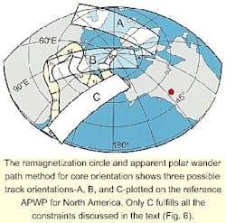
Instead of creating a single arc from the set of possible declinations, however, as described above for a single magnetization component, a series of "tracks" are created from one magnetization component to the other (Fig. 6). These tracks can then be compared to the APWP.
Several constraints can be placed on the track:
*If the depositional age of the sampled formation is known, the correct track cannot intersect the APWP at an older time.
- The endpoints of the correct track must both intersect the APWP.
*In most cases the first-removed component is younger than the second-removed, and the relative intersections of the correct track and APWP must be consistent.
Once the two intersections with the APWP have been determined, the true declination of both magnetizations can be back-calculated to determine core orientation. Again, the presence of a structural tilt will affect the results and must be corrected prior to using this method.
Limitations
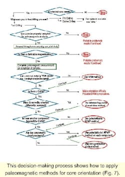
Table 1 presents a summary of the advantages and disadvantages of core orientation methods, both paleomagnetic and non-paleomagnetic, while Fig. 7 outlines the decision-making process for utilizing paleomagnetic methods.
Because the core has to be reassembled into segments and plugs drilled, it has been found that the core tends to be unusable if it:
*Is essentially rubble, consisting of heavily fractured intervals or thinly interbedded lithologies that break apart upon coring.
*Has many missing pieces.
*Is too small for plugs to be drilled.
*Has been extensively sampled for whole core analysis-some jurisdictions do not permit sampling of such core and whole-core petrophysical analysis tends to degrade the VRM.
Therefore, the ideal core for paleomagnetic analysis has a diameter greater than 2.5 in. (6.5 cm); individual pieces that are > 2-3 in. long; segments that are a minimum of 2-3 ft long; and sufficient untouched core material that allows for a reasonable sampling density.
Problems can occur if individual core pieces have been inadvertently placed into their boxes upside down. In cores where the segment lengths are short and the number of pieces fitted together is small, several inverted segments have been found.
Thus, in an ideal situation, a segment should consist of pieces from more than one box and, if a segment is contained within a single box, the researcher must be watchful for core inversions.
Reliable recording
The methods described above presume that the magnetization can be used to record the (past) Earth's magnetic field accurately, and that it can be measured using the available magnetometer. To a large extent, the first constraint is dependent on the second.
Almost all lithologies carry a magnetization imprint, however, the weaker the imprint of magnetization, the more difficult it is to measure. The superconducting magnetometer at Windsor can measure magnetizations as weak as <5x10⁻⁶ amp/m, a standard that few other magnetometers in the world can match.
Most of the dolomites and limestones measured from Western Canada have natural remanence magnetization intensities that are only one or two orders of magnitude greater. Thus, these studies show that only a very small percentage of samples, <5%, do not carry a measurable ChRM that cannot be used for paleomagnetic studies.
Acknowledgment
The authors wish to thank Julie Clarke, Jeff Lonnee, and the following companies for contributions to this article: Anderson Oil & Gas Ltd., Husky Oil Ltd., Rigel Oil & Gas Ltd., and Shell Oil Ltd.
References
- Kodama, K., "Paleomagnetism of granitic intrusives from the Precambrian basement under eastern Kansas: orienting drill cores using secondary magnetization components," Geophysical Journal of the Royal Astronomical Society, Vol. 76, pp. 273-87, 1984.
- Rolph, T.C., et al., "Viscous remanent magnetization: a tool for orienting drill cores: Applications in Hydrocarbon Exploration and Production," Geological Society Special Publication 98, pp. 239-43, 1995.
- Lewchuk, M.T., Al-Aasm, I.S., Symons, D.T.A., and Gillen, K.P., "Dolomitization of Mississippian carbonates in the Shell Waterton gas field, southwestern Alberta: Insights from paleomagnetism, petrography and geochemistry," Bulletin of Canadian Petroleum Geology, Vol. 46, pp. 387-410, 1998.
- Kirschvink, J.L., "The least-squares line and plane and the analysis of paleomagnetic data," Geophysical Journal of the Royal Astronomical Society, Vol. 62, pp. 699-718, 1980.
- Fisher, R.A., "Dispersion on a sphere," Proceedings of the Royal Astronomical Society, Series A, Vol. 217, pp. 295-305, 1953.
- Butler, R.F., "Paleomagnetism: Magnetic Domains to Geologic Terranes," Blackwell, Oxford, 1992.
- Van der Voo, R., and Watts, D.R., "Paleomagnetic results from igneous and sedimentary rocks from the Michigan Basin borehole," Journal of Geophysical Research, Vol. 83, pp. 5844-48, 1978.
- Symons, D.T.A., Enkin, R.E., and Cioppa, M.T., "Paleomagnetism in the Western Canada Sedimentary Basin: Dating fluid flow and deformation events," Bulletin of Canadian Petroleum Geology, Vol. 47, pp. 534-47, 1999.
- Tarling, D.H., "Palaeomagnetism," Chapman and Hall, London, 1983.
- Besse, J., and Courtillot, V.E., "Revised and synthetic apparent polar wander paths of the African, Eurasian, North American and Indian Plates, and true polar wander since 100 Ma.," Journal of Geophysical Research, Vol. 96, pp. 4029-50, 1991.
The Authors
Maria Cioppa has been working on a post-doctoral fellow at the University of Windsor since 1997, investigating the use of paleomagnetism to orient core and to date diagenetic events in the Western Canada Sedimentary Basin. She holds a BSc (1990) in geology from Carleton University, Ottawa, an MSc in earth and ocean sciences from University of Victoria (1992), Toronto, and a PhD in geological sciences from Lehigh University (1997), Bethlehem, Pa.
Kevin P. Gillen is president of Vox Terrae International Co., a company he formed in 1994 that studies various aspects of fractured reservoirs using log and core information. After 1988, he joined Shell Canada Research. Gillen obtained a BSc (1985) in geological engineering from the University of Windsor and an MSc (1988) in geophysics from the University of Alberta.
Michael Lewchuk is currently a staff scientist at the University of Oklahoma's School of Geology and Geophysics. He obtained his doctorate from the University of Western Ontario. Lewchuk spent 2 years as an NSERC post-doctoral fellow, dividing his time between the USGS in Denver and the Institut de Physique du Globe in Paris.
David T. Symons is professor of earth sciences and a principal of Canterbury College, University of Windsor, Windsor, Ont. After a year as a post-doctoral fellow at the University of Newcastle-upon-Tyne, UK, and 3 years as a research scientist at the Geological Survey of Canada, he joined the University of Windsor in 1970 where he teaches geophysics and structural geology. Symons holds a BASc in geological engineering, a PhD from the University of Toronto, and an MA from Harvard University.
