Competitive pressure introduces disparate bicenter design
In response to competitive pressures introduced by recent shoe drill-out achievements, major bit manufacturers have begun using disparate bit features to drill reliably through plugs, packers, and formations in one run, while retaining toolface control throughout complex build and tangent sections.
A steering wheel
Offshore applications continue to dominate the bicenter bit market as complex well profiles require reaming operations to complete wells with larger production strings.
Although bicenter bits have long played a large role in these activities, competing with underreamers for market share, only with recent advances in force balancing and cutter placement has there been a step-change in the development of this technology.
"For us and the industry as a whole, there was a change last year when DPI [Diamond Products International Inc.] proved they can drill out float equipment with their bicenter bits (OGJ, May 1, 2000, p. 95)," says Graham Watson, senior design engineer for Reed-Hycalog.
Yet this step-change has introduced technical barriers for all companies as they try to compete in this expanding market. For example, while fundamental knowledge of cutter placement and force balancing helped produce an efficient drill-out bit, problems associated with directional control may offset this advantage if the design does not consider steerability issues.
"We decided to produce not just a bit that can drill out, but to look at what the industry wanted," Watson said, referring to the following objectives:
- Drill out the shoe and formation in one run.
- Maintain toolface while sliding.
- Reduce dropping tendencies during build and tangent sections.
- Eliminate the need to use positive displacement motors with higher angle bent housings, a result of long bicenter bit length.
The design
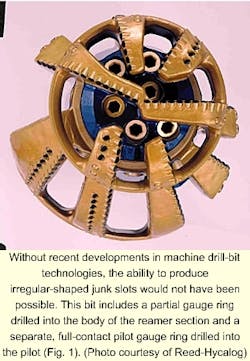
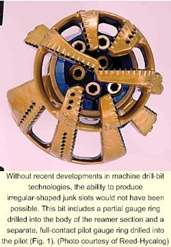
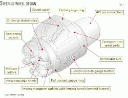
Whereas a normal bicenter bit includes individual blades for the reamer and pilot gauge pads, Reed-Hycalog's new design incorporates two components (Figs. 1 and 2):
- A partial gauge ring that includes enclosed, irregular-shaped junk slots drilled into the body of the reamer section.
- A separate, full-contact pilot gauge ring that includes enclosed, irregular-shaped junk slots drilled into the pilot bit (steering wheel).
"This is the first product with an enclosed junk slot on a bicenter bit," Watson says. But instead of discrete gauge pads placed strategically around the bicenter, a continuous 360° gauge pad (steering wheel) built into the pilot provides lateral stability needed to maintain toolface.
Thus, if bicenter bits are to be used in complex well configurations, they must overcome inherent tendencies to drop angle in inclined wells.
Basically, the asymmetric geometry of these bits, coupled with the effects of gravity, preferentially force bits to cut along the low side of the hole.
"The strong dropping tendency of bicenter bits means that it is much more difficult to use bit weight to control inclination," says Steven Hart, design engineer for Reed-Hycalog. As a result, operators spend more time sliding while drilling the build and tangent sections, reducing overall penetration rates.
To overcome this problem, the reamer and pilot gauge rings create two non-aggressive bearing surfaces, in turn limiting its ability to cut sideways. Based on this premise, engineers expect that the "steering wheel" will drill in any direction with a reduction in sliding time, making inclination more controllable as various bit weights are applied.
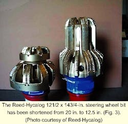
Another innovative feature, serving to reduce required bend angles in the mud motor, includes a reduction in overall bit length from 20 to 12.5 in. (Fig. 3). This allows for decreased mud-motor bends as the replacement of traditional long blades with short gauge contacts reduces the overall length of the bit embedded within the gauge rings.
"The beauty of the 'steering wheel' concept is that it provides the benefits of a long-gauge bit in a fraction of the length. It has therefore helped us to meet our performance objectives," Hart said.
Metal-cutting technology
Two years ago, however, the ability to manufacture integral gauge rings would have been impossible. Currently, bicenter bits are manufactured from a single block of steel. "You start with a solid piece of material and machine the cutter slots, water ways [nozzle ports], and enclosed junk slots [directly in the bicenter] using drill bits with tungsten-carbide tipped drill bits," Watson said.
Because machine drill bits must cut irregular-shaped junk slots, needed to circulate drill cuttings and fluids up the annulus, manufacturers must overcome problems associated with an interrupted cutting action. "It is easy to produce a nice round hole with 1 x 12-in. long drill bit-where you can use a long tool." But the cutting loads are spread around as it drills a full circle.
"When first asked how could we machine in closed junk slots in steel, it soon became apparent that just drilling large holes would not provide enough junk-slot volume," said Paul Ellis, senior production engineer for Reed-Hycalog. "We also saw that the varying break-through angles would soon break a high-speed drill."
At this time, Sandvik Coromant Co., Houston, launched a line of "four-times diameter indexable machine drill bits." These tools, ranging from 12.7 to 58 mm in diameter, are now regularly used in manufacturing the Reed-Hycalog "steering wheel."
Drill-out test
Prior to bringing this bit design to market, a full-scale test was carried at Weatherford Inc.'s test rig in Houston. The test was made as realistic as possible by running the bit inside casing at a true vertical depth of 1,000 ft on a positive-displacement motor (PDM) with a bent housing. Drilling parameters included pumping fluids at 500 gpm while turning the PDM at 100 rpm (20 rpm at surface).
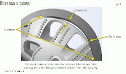
The new design successfully drilled out a rubber wiper plug, cement, and float collar (Fig. 4). To reveal the resulting damage if the bit was rotated at one position for an extended time, the bit was circulated for 15 min at one spot, picked up 18 in., and then rotated again for another 15 min. During the test, the bit was rotated inside the casing for over 1 hr.
The circulated mud was passed through a very fine mesh, and two possum belly magnets were used to collect any metal shavings. After 1 hr, less than 3 oz of metal shavings were collected. After the casing was retrieved and sectioned, a detailed study showed virtually no wear to the bit or the casing.
This test was further validated by use of an existing design of bicenter bit that had been previously rotated inside the casing on a commercial well but had produced a lot of metal cuttings. If this bit had not produced cuttings it would have meant an easy test situation.
However, the second bit produced a lot of metal cuttings as it created deep grooves in the casing. After 30 min of rotation, this bit produced six times the amount of metal cuttings as compared to the new bit produced in 1 hr.
Three runs
Since this time, the Reed-Hycalog bicenter bits have been run in three wells.
The first application was a 105/8 x 121/4-in. bicenter run for Shell Offshore Inc. in the Green Canyon block, Gulf of Mexico (GOM). In this case, the bit was not used to drill out but instead as a steerable bit replacing a competitor bicenter. All in all, the steering wheel drilled about 1,500 ft.
The second run, which consisted of an 81/2 x 97/8-in. bicenter steering wheel, also took place on a Shell GOM well in the Mississippi Canyon block. Yet in this case, the bit successfully drilled through 400 ft of cement, the shoe, and into formation where it was pulled 4,000 ft later.
Finally, the third real-world test, which used a 105/8 x 121/4-in. bicenter across an openhole section of 100 ft, took place mid-April for Union Pacific Resources Corp. offshore Louisiana in the Terrebonne Parish (Turtle Bayou field).
According to Don Pearce, drilling superintendent with UPR, the steering wheel provided two advantages: Improved cementability and an increased chance of running casing to TD. "We wanted more hole clearance to improve our chances of running and cementing the 95/8-in. liner below the 113/4-in. casing string."
Although the 105/8 x 121/4-in bicenter bit run was used to drill out the shoe, it was not used to increase subsequent string ODs. Instead, UPR opted for an enlarged annular hole space that allowed for increased cement volumes, providing a more thorough bond.
Altogether, the Reed-Hycalog DS152 HDF drilled 3,300 ft in 115 hr to a depth of 15,400 ft.
Ream while drilling
A new drill-out steerable ream while drilling (SRWD) tool, manufactured by Hughes Christensen, also eliminates a trip as it can drill-out float equipment, cement plugs, and formation.
In comparison to other tools, however, this design uses a cross-over reamer positioned between the bottomhole assembly and drill bit, allowing operators to run a roller-cone or PDC pilot bit to optimize performance in a particular formation (Fig. 5).
"You're not stuck with someone else's design of a bicenter bit," says Wayne Squires, president of Pioneer Drilling Co. Squires says the RWD provides several advantages.
First, "We can increase hole size underneath the protection casing to 97/8 in. from the traditional 81/2 in. However, because we run the same size casing (across the same zone), the increased [annular] space reduces the equivalent circulating density (ECD) through a decrease in fluid pressure."
For companies like Cabot Oil & Gas Co., this advantage has also reduced problems associated with lost circulation while eliminating casing failures through the placement of extra cement in the annulus. Additionally, "We drilled five wells for Forest Oil Co. and eliminated liners on four wells," Squires said.
Because reaming technologies must also address directional and slimhole applications, Hughes Christensen developed three hole-opening systems: RWD, SRWD, and slimhole ream while drilling.
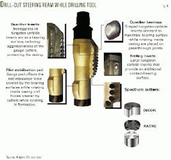
The RWD tool includes a number of innovations, including hole opening blades and a pilot stabilization pad (Fig. 6). The hole-opening blades allow a more equivalent depth of cut for the four blades.
Additionally, the pilot stabilization pad, consisting of a nonaggressive pad, serves to stabilize the entire assembly in the pilot hole. The RWD and SRWD are the only tools available that offer pilot bit options based upon application.
Drill-out development
Until recently it was not possible to drill-out cement plugs without damaging the RWD tool or the inside diameter of the casing. Problems encountered while rotating inside the casing included damaged PDC cutters positioned close to the pass-through area along with worn casing.
Additionally, other parts of the tool that contact the casing may be damaged as well as cutters in the center of the pilot bit that rotate backwards while drilling the float equipment.
Full-scale laboratory tests were performed at Hughes Christensen's drilling simulator in The Woodlands, Tex. A standard 97/8-in. SWRD tool was used to drill through casing cemented into an Indiana limestone test block. The test results showed mild vibrations between 100 and120 rpm; however, no cutter damage resulted.
The tool drilled out below the casing and transitioned from pass-through to near full drill size within 12 in. The final caliper was measured as 91/2-in. and 7-in. vs. the predicted 97/8 in. and 61/2 in. The borehole and the casing wall remained in excellent condition.
A small amount of wear indicating casing contact on the gauge cutters was observed but with no significant damage. A few steel shavings were additionally found from the casing; however, the tool drilled out below the casing and gradually opened up the hole. The inspection of the ID casing wall revealed minor scarring that did not exceed 1/32 in. - 1/16 in.
SWRD
The drill-out SRWD technology was developed into a commercial product from conception in 6 months. Key elements include a pass-through bearing surface that allows rotation in the casing, sharp polished cutters, and the pilot stabilization pad.
The pass-through bearing guard contains nonaggressive tungsten-carbide inserts that act as a bearing surface. They are placed on the first blade upon pass-through and reduce the aggressiveness of the gauge cutters protecting the casing. The pass-through bearing limits lateral motion and absorbs impact to protect the cutters.
The guardian inserts, which consist of nonaggressive tungsten carbide inserts, are placed on the blades that encounter specific pass-through contact points. They are oriented to maximize the bearing surface in the casing while limiting lateral motion.
The trailing guardian inserts are positioned on the trailing blade, providing additional contact with the casing wall while reducing lateral motion.
Two types of cutters are also used to reduce casing wear while providing adequate cutting structures for drilling out the shoe and formation. Spectrum cutters utilize increased diamond table thickness with large chamfers for improved durability.
These cutters, which are used on the pilot-bit gauge and near pass-through blades, reduce the gauge cutter aggressiveness and protect casing and cutters while rotating inside the casing.
In addition, Specturm DIAX 45 cutters provide increased diamond table thickness with a large chamfer for improved durability. This reduces gauge cutter aggressiveness protecting casing and cutters while rotating inside the casing. These cutters are used on the gauge and near pass-through blades and are should also be used on gauge of the pilot bit when PDC is the bit of choice.
RADXC cutters are used on the remaining blades. These cutters have an engineered planar interface that reduces internal stress and are well suited for applications where impact and downhole vibration is an issue.
Finally, the pilot stabilization pad offsets the resultant force created by the bearing surface and minimizes bending. The pilot stabilization pad limits the depth of cut on the pilot in the casing and provides one of the pass-through contact points. It improves the transition from pass-through to drill size.
Testing
Nine prototype RWD assembly tests were conducted at The Woodlands' facility and the BETA test site near Tulsa, Okla.
At the BETA site, a 171/2-in. hole was drilled to a depth of 310 ft. A Weatherford Gemeco cementing plug was then cemented into the test hole. Next, a 121/2-in. drill-out SRWD and 8-in. mud motor with a 1.75° adjustable kick-off setting was used to test the directional motor and drill out tool.
The procedure then consisted of drilling through the cement then stopping above the plug without string rotation. The bit and SRWD assembly were inspected for wear prior to drilling out the float shoe.
Next, the float and shoe equipment were drilled without string rotation to 315 ft, taking 45 min to drill the float equipment. The entire assembly was pulled after the run where inspection revealed minimal wear on the pass-through bearings and no major cutter damage. Two cutters on the PDC pilot bit, however, were damaged due to aggressive back rake on the gauge cutter. The casing caliper showed no unusual wear.
South Texas
Next, Pioneer Rig No. 4 performed an actual field run in Hidalgo County, Tex. The 97/8-in. drill-out SWRD worked as intended and drilled the cement, landing collar, and float shoe in 2.5 hr. Drilling parameters included 4,000-8,000 lb bit weight at 60 rpm and 480 gpm of mud flow. Even wear was observed on the inserts and bearings and a drill-out trip was eliminated.
Based on the development work, a series of recommended operating practices was developed. Pilot bit recommendations include running PDC bits with nonaggressive gauge cutters, tending towards a higher blade count. When roller cone bits are used, some type of stabilization system is recommended to limit side cutting.
With a steerable motor assembly, a slow-speed, high-torque motor is recommended and the drill string should not be rotated. Additionally, the mud pumps should be brought up to normal operating speed once the cement is tagged.
The bit weigh should be kept between 2,000 and 8,000 lb, allowing for a minimum weight to produce an acceptable penetration rate.
While drilling the float collar and shoe, slow penetration rates should resemble the performance of other drill bits, depending on the pilot bit used (PDC or tricone). More weight may be applied with caution if required.
Drilling out on rotary takes a different approach. When the cement is tagged, the pumps should be brought up to maximum flow rate while holding the rotary speed in the 60 to 70 rpm range.
WOB should remain between 2,000 and 4,000 lb and a minimum weight that will produce an acceptable rate should be run. If excessive vibrations are encountered while drilling cement, rotary speed should be varied until a speed is found where smooth running conditions prevail. While drilling the float collar and shoe, the drill rate may fall off; therefore more weight may be cautiously applied to produce an acceptable rate.
When tripping in and out of the hole, the operator must pay special attention when passing through tight spots, the casing shoe, or any other problem areas. The drill-out SRWD should be slowly pulled back through the casing shoe to insure no damage is done to the shoe or tool on the trip out.
While the drill-out SRWD tool is designed for casing rotation, it is recommended that the testing of mud motors or MWD tools be conducted at the surface before picking up the tool.
