Engineers overcoming bicenter drillbit design hurdles for offshore applications
This is the first of two articles on overcoming hurdles in bicenter bit design for offshore applications. This week's article provides examples and technical explanations concerning the performance and design issues for this rapidly advancing technology. Part two will show how drillbit manufacturers, each developing unique bicenter technologies, seek to provide their own solutions to problems.
Recent developments in bicenter drillbit design have overcome many of the problems that once precluded their use in costly offshore operations, now allowing operators to eliminate many nondrilling activities, such as bit trips, while improving drilling performance.
This first of a two-part series provides examples and technical explanations concerning the performance and design issues for this rapidly advancing technology. The conclusion provides further information on how various drillbit manufacturers, each developing unique bicenter technologies, seek to provide their own solutions to problems that have haunted drillers over the past 40 years.
Operators such as Chevron Corp., Shell Offshore Inc., Spirit Energy 76 Deepwater, and Statoil Exploration (US) Inc. now use bicenter drillbits to:
- Drill out the shoe then drill ahead in one run.
- Optimize clearance between casing strings and hole sizes.
- Geosteer without loss of directional control.
- Set a larger diameter casing or liner string at TD.
Chevron's Genesis
Chevron recounted its success with bicenter drillbits in its Genesis oil field development project in the Gulf of Mexico.
According to Curt Newhouse, Chevron's Genesis project drilling superintendent, "Instead of doing it the old-fashioned way by running a rock bit to drill the float equipment and hole section, then making a bit trip to underream the interval, we now drill out the float equipment, perform a leak-off test, then drill the entire hole section with a bicenter in one run, saving at least one trip."
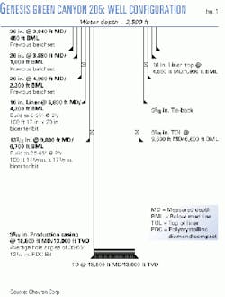
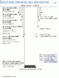
The primary reason why Chevron uses bicenter bits, however, is to set 9 5/8-in. casing through the primary producing intervals to TD (Fig. 1), thereby allowing larger completions to be run that result in higher flow rates.
The first section on the more recent wells (A-5 and A-6) consisted of drilling out of the 20-in. casing, previously batch-set at about 2,300 ft below the mud line (BML). However, because a 171/4-in. ID landing ring was required inside the 20-in. casing string to hang a 16-in. liner, this imposed drillbit constraints that typically would have required extensive underreaming-a costly and time-consuming affair with a high degree of mechanical risk.
Because these wells are drilled directionally and because external upsets on the casing connections can produce tight tolerances between the casing and wellbore, it becomes necessary to maintain a large annular interface that is not readily configured with conventional casing and drillbit sizes.
Saving trip time
Accordingly, the first section, which is the first of two bicenter hole section runs, included drilling out the shoe into open hole with a Diamond Products International Inc. (DPI) bicenter bit, incorporating a 17-in. pass-through size and 20-in. rotational OD (17 x 20-in., Fig. 2). This allowed Chevron to set 16-in. casing 2,000 ft below the 20-in. casing shoe at 4,300 ft BML.
The wells were also kicked off in this interval to hole angles reaching 30-45 degrees at casing point, with minimal directional control problems. This appears to be one of the first projects to kick off directional wells with this size of bicenter bit.
For the second interval, the same procedure takes place but instead entails running 133/8-in. casing to about 10,500 ft measured depth (MD, 6,700 ft BML) with a 141/2 x 171/2-in. bicenter. Again, the only other option would be to drill the shoe out into formation with a 143/4-in. rock bit, then underream to a larger hole size.
Finally, 121/4-in. hole is drilled with a conventional PDC bit to TD, after which 95/8-in. casing is set anywhere from 15,000 to 21,000 ft MD. Altogether, bicenter bits saved at least two bottomhole assembly trips as compared with conventional operations that required drilling the hole section with a regular bit-especially in directional wells-then tripping out for the underreamer.
The bottom line
"The last well, A-6, went flawlesssly," Newhouse said. "We drilled to 16,501 ft MD in 14.9 days from spud. This included running two casing strings, an inner drilling riser, and so on." And taking into consideration straight drilling time (excluding casing and riser operations), which averages 120 fph in the upper- hole sections and 150 fph in the 121/4-in. section, Chevron has progressively improved its performance well after well.
For example, Newhouse said, "The first couple of wells took 9.5 days to reach 16,500 ft, excluding casing runs, etc., while our last well, the A-6, took only 4.8 days of straight drilling time. Thus, with total day costs at about $80,000/day, Chevron now saves about $1.2 million/well as compared with the beginning of the Genesis project."
Another way to compare performance improvements is by taking a look at the authority for expenditures (AFEs) developed 4 years ago. "Day curves were developed based on offset data and the conventional technology and procedures of the time, which was basically drill then underream," Newhouse explained.
As such, about 20 trouble-free days were budgeted for the time between drilling out the 20-in. shoe until the 141/2 x 171/2-in. hole interval reached TD. On the most recent well A-6, these same operations were completed in 5.5 days, again saving about $1.2 million.
Newhouse notes that, although bicenters have been around for awhile, their applications have generally been limited to small-hole sections (sidetracks) using oil-base mud. "With the latest generation of bicenters, we are now using them in large-hole sections with water-base muds."
The only current drawback involves some difficulty in achieving high penetration rates with mud weights greater than 13.5 ppg.
A design rehaul
The original concept of the bicenter bit, which included a pilot bit combined with a reamer where all of its cutters are placed to one side, was developed about 40 years ago. Essentially, this technology allowed the bit to slip down through a smaller hole after which rotation allowed the operator to bore an oversized section.
Obviously, this concept held great promise for operators who wished to increase hole and casing sizes under a variety of scenarios.
Nevertheless, the technology remained on the sidelines, as inherent stability problems in drillbit design-dominated by the asymmetrical position of the reamer blade-resulted in either undersized-hole sections, short bit runs, high torque levels, or difficult-to-control angle-building tendencies.
In the last 10 years, however, advances made in force balancing and cutter placement, aided by insights gained in polycrystalline diamond compact (PDC) bit design, have helped to improve bicenter performance. "In the mid-1980s, we recognized that one of the problems with PDC bits is that they don't drill very smoothly," said Coy Fielder, engineering manager for DPI, Houston. Thus, a tremendous effort was put forth by the industry to improve bit stability.
"In the early 1990s, it then dawned on us that the same problem we were having with PDC bits also affected bicenter bits, where one of the critical steps in making bits drill smoother is to improve the force balance."
Essentially, this means that the cutting forces that encircle the bit must cancel each other out, eliminating any bit-centric effects that can push it off to the side. "With a drillbit, you can get this force (net imbalance) down close to zero. But with the way bicenter technology was then, the net imbalance, without changes, was about 30%. Thus, 30% of the bit weight was actually pushing the bit off to the side."
The first breakthrough in improving the force balance of bicenters was made 5 years ago, when engineers redesigned the pilot so it would push against the reamer. "Whereas before," Fielder said, "people worked with cutter placement to try to get zero imbalance, we actually designed the pilot bit with a high degree of imbalance, and then oriented it so that the high imbalance of the pilot would offset the high imbalance of the reamer."
By making changes to cutter placement, for both pilot and reamer sections, bit designers were able to cut this force imbalance in half-to about 8-15%-introducing a major improvement that was a key step in producing a commercially viable product.
Unfortunately, this magnitude of improvement, as related to the issues of stability, still fell below that of a conventional bit, remaining at this level until early 1999.
"Late in 1998, we began a project to move bicenter bits to the next level. Our main goal was to produce a bit that would eliminate trips by adding the capability to drill out and drill ahead with the same bit," Fielder said. Typical operations begin by drilling the plugs and float collar with a conventional bit. Then the crews must make a bit trip before running the bicenter.
"We were able to do this, but in doing so, we also came up with a new concept that further reduced the force balance, dropping the imbalance down in the range similar that of a conventional drillbit," Fielder said.
Two problems
The issue of producing a bicenter that can drill out can be broken down into two separate problems: off-center rotation inside casing and the prevention of casing enlargement. Conventional drillbits do not rotate off center in casing or formation, so a new method of cutter placement was also required for the bicenter design. Thus, certain compromises, attenuated by design enhancements, had to be made.
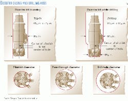
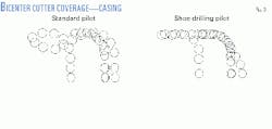
First of all, bicenter bits utilize two drilling axes that shift from casing to openhole operations (Fig. 3). When a bicenter bit is rotated inside casing, the center of rotation shifts away from the geometric center of the pilot. This causes a major misalignment of the cutters that make it difficult to drill out plugs and floats.
Second, because the primary function of the bicenter bit is to enlarge the hole as it drills ahead, extensive casing wear can occur if the bicenter is not modified to prevent enlargement while inside casing.
"When it's drilling in the hole, and you've done your design right, the bit rotates around the center of the pilot bit, which then allows the reamer to sweep around and open up the hole. What that means is that, as the axis shifts to the side and is rotated-as happens when the bit is rotated in casing-the cutters will cut a different path than what they were designed to do (Fig. 3). "This makes the cutter coverage real strange," Fielder said.
The solution to this problem was to design cutter placement with continuous coverage from the center to the outside, regardless of which of the two centers it rotates around. "It's pretty straightforward but a very difficult 3D problem to solve," he said. In all, it took DPI 4 months to design its first next-generation bicenter bit. "It was trial and error..., but we now have something that has cutters that will cut through the shoe and float equipment as well as drill properly in formation."
Ductile steel, back rake
This left the second problem to solve: keeping the bicenter bit from enlarging the inside of the casing. Fortunately, the company's experience with steel-bodied products provided essential clues in the next design stage.
"It turns out that since steel is ductile, it doesn't like cutting elements (PDCs) with a high back rake," Fielder said. "Basically, the cutter will slide over steel" while allowing it to cut formation as needed.
"What it amounted to was [that] we decided to place these cutters in all positions that might contact the steel inside the casing while using 'normal' cutter in positions that cut ahead. This allowed us to rotate inside casing in a manner that allowed us to drill ahead but with extreme difficulty in cutting to the side," he explained.
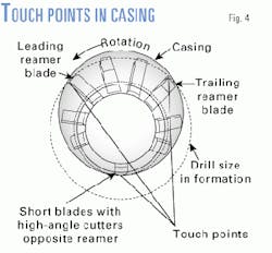
As a bicenter bit rotates inside casing, it has three primary points of contact with the casing: with the first point of contact located at the leading reamer blade, the second at the trailing reamer blade, and the third positioned directly opposite the primary reamer blades (Fig. 4).
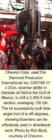
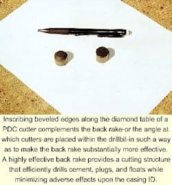
By placing high back-rake cutters in these positions, casing damage can be minimized. And by adding beveled edges inscribed on the outer edge of the PDC cutters' diamond tables (see photo, below), the effective back rake was increased to as much as 60
This insight was an important step in producing a bicenter that could drill out. However, because of all the design changes, it made the force imbalance worse. "So we started looking at what we could do with the forces," Fielder said.
To do this, DPI reduced the pilot bit in sized, and small blades were added to the reamer-in positions opposite the full size reamer blades. This helped but was not enough to produce the desired force balance.
"So we then made all the cutters on these short blades high-angle cutters," Fielder said. "Yet, unlike the earlier case, where high back-rake cutters were positioned near the casing wall, the high-angle cutters on the short blades were positioned where they would come into play to drill ahead. "Of course, that would increase the drilling force on the cutters, but also-since they are positioned opposite the reamer-it would shove out against the reamer."
Thus, the key to reducing the force imbalance came by adding small blades to the reamer and placing high-angle cutters on these so as to push against the reamer. "So now you have the pilot pushing against the reamer, and you've got these little blades opposite the reamer pushing against the reamer, with the net effect that the force balance has been improved to nearly the same level as [with] a conventional PDC bit," he said.
This resulted in two components from which to offset the balance, where before there was only one.
To date, more than 100 casing-shoe drill-out runs have been made with DPI bicenter bits in the Gulf of Mexico, Rocky Mountains, Texas, Latin America, North Sea, and Africa for British-Borneo Oil & Gas PLC, BG PLC, Elf Aquitaine SA, BP Amoco PLC, Texaco Inc., and Forest Oil Corp., among others. With sizes ranging from 33/8 x 33/4 in. to 171/2 x 22 in., future applications may include expandable casing, multistring well plans, equivalent circulating density reduction, reentry, and gravel-pack operations.
Shell's Europa
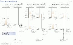
The very first well drilled with the new bicenter bit design provided a unique test opportunity across three intervals: A vertical leg, angle-build section, and tangent (Fig. 7). "With a bit and underreamer, you can't do directional work," said Waitus Denham, senior drilling engineer for Shell's Europa development project in the Gulf of Mexico. However, "with the bicenter bit, we can drill out the shoe, drill ahead, and even hold angle," he said.
Overall, the company saved five trips by using a bicenter drillbit. Again, the project depended on running a larger-than-normal production string to TD, "which couldn't have been done with a standard program."
First, a 12 1/4 x 143/4-in. DPI CSD144 (DPI), with 13-mm cutters on a 1.5 degrees x 95/8-in. steerable motor was used in the vertical section (Fig. 6a), reaching TD at 12,300 ft. The bit drilled 831 ft of cement, a float collar, a float shoe, 40 ft of rathole, and 5 ft of formation in 7.5 hr.
After testing the shoe, the same bit continued to TD in 26.5 hr. "If available, I don't think we would find much difference between the performance of a PDC bit and the bicenter, using comparable bit sizes if available," Denham said. An 113/4-in liner was then run to TD without any tighthole problems.
Next, a 105/8 x 121/4-in. CSD133 bicenter was used to save two trips (Fig. 6b). Denham says the typical procedure would include drilling to the top of the 113/4-in. liner with a 121/4-in. bit, drill out the liner with a 105/8-in. bit, and then drill formation with a 105/8 x 121/4-in. bicenter.
Instead, the bicenter drilled a 121/4-in. hole to the top of the liner, a 105/8-in hole inside, and then a 121/4-in open hole section underneath. The entire interval averaged 100-120 fph, building angle to 13.5
The third interval underneath the 95/8-in also saved on two trips (Fig. 6c), with the use of a newly designed CSD133, 81/2 x 97/8-in. bicenter bit. It drilled to TD in 33.5 hr, maintaining angle and direction to TD at 18,015 ft MD. The bicenter saved 12.2 hr of trip time to clean out the top of the liner and 16.7 hr of trip time to drill out the shoe. As compared with offset wells, drilling performance improved by 5.4 hr.
Reference
1. Denham, D., and Fielder, C.M., "Bi-Center Innovations Impact Deepwater Drilling," IADC/SPE paper 59239, presented at the IADC/SPE Drilling Conference, New Orleans, Feb. 23-25, 2000.
