Burlington reverse circulates cement, sets world record
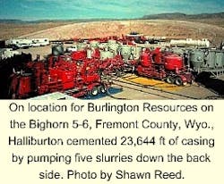
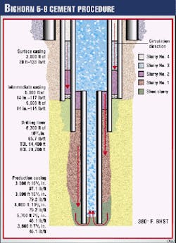
Burlington Resources Inc. and Halliburton Energy Services, Casper, successfully cementing 23,644 ft of casing on the Bighorn 5-6 well in Fremont County, Wyo. (Fig. 1).
With emphasis placed on a thorough cement job, conducted under extreme bottomhole temperature conditions that must account for slurry set-up time, the companies reverse circulated cement down the annulus then up through the casing.
"We designed the whole system so that the cement sets [hardens] from bottom to top while minimizing transition times. In other words, you maintain the hydrostatic pressure of the fluid column on the formation so the gas can't migrate in," says Shawn Reed, technical specialist for zonal isolation, Halliburton.
Compared with conventional multistage cement procedures, in which operations require multiple plugs and a float to displace drilling fluids and cement, reverse circulation eliminates the need for such equipment, minimizing the risk of mechanical failure.
A clean hole
Good mud conditioning and cuttings removal provide key components in performing a successful cementing operation. "You clean the hole of cuttings prior to cementing in the conventional manner because annular velocities are nearly three times faster in the annulus than through casing," says Reed.
Once the cuttings are then cleaned up, the direction of circulation is reversed and an additional circulation is performed.
"The system needs to be clear of solids because once the fluid moves into casing, the fluid velocity slows down and you could have a problem with carrying the cuttings out of the well. This could allow the cuttings to fall back in and bridge you off."
The advantages of the reverse circulation procedure also include a substantial reduction in equivalent circulating densities (ECDs), shortened time requirements needed to place the cement, customized setting order for the various cement stages, and a reduced need for retarders.
Friction
In every cementing process, it is critical to stay within rock-property and reservoir-pressure tolerances. In other words, the fluid column weights must be maintained above the fluid pressure of the reservoir yet below the fracture pressure of the exposed formation.
For the conventional process, however, the exposed formations encounter the hydrostatic pressure of the fluid above it in addition to the frictional pressures needed to pump that fluid.
Thus, if the frictional component, as defined by pump rates, fluid rheology, and the specific wellbore geometry, becomes too high, it can break down the formation resulting in lost cement returns.
Friction increases dramatically as the annular space decreases. "By using the reverse circulation process, we can take advantage of gravity," Reed says. "As you reverse circulate, you subject the zone to hydrostatic pressure, but the friction factor diminishes significantly."
Another key issue in these deep hot jobs, with bottomhole static temperatures greater than 400° F., concerns the duration of cement placement. "You can end up having long placement times as much as 10-12 hr," he says. Thus, for a conventional procedure, lead cements have to be retarded (delayed hardening) to compensate for bottomhole circulating temperature and extended pump time requirements.
"When we place the jobs from a reverse basis, however, we can take a lot of the retarder out, reducing our placement time to 3-4 hr while placing competent cement from top to bottom," Reed says.
Slurries
The job procedure went as follows (Fig. 1):
- Hold safety meeting and cover all aspects of operation.
- Rig up one 2-in. line from the two cement trucks. Connect the line into both outlets on the B-Section of the wellhead configuration positioned 180° apart.
- Make sure everyone stands away from lines and test lines, which can reach 4,000 psi.
- Open up valves to casing and establish pump rate of 8 bbl/min with modified dual spacer.
- Pump 80 bbl of modified dual spacer weighted to 14.7 ppg. This procedure served to displace drilling fluids ahead of the cement, helped sweep the hole of cuttings and other contaminants, and water wet the hole to ensure a good cement bond.
- Mix and pump 75 sacks of foamed scavenger slurry. Because foam has excellent displacement mechanic characteristics, it serves to sweep the residual mud left from the dual spacer. The base weight is 17.0 ppg, and the foamed weight is 15.0 ppg. Pump this slurry at 3 bbl/min liquid rate and 1,650 scf/min nitrogen rate where the cement and nitrogen is comingled.
- Resume the liquid pump rate to 8 bbl/min liquid rate after the nitrogen is shut down.
- Mix and pump 625 sacks of slurry No. 1 (shoe slurry), weighed at 17.0 ppg, over an interval of 4,000 ft (top of fluid = 19,700 ft). About 700 ft of cement will in the end be pumped into the casing, allowing the initial contaminated cement to be displaced away from the formation-casing annulus.
- Mix and pump 725 sacks of slurry No. 2, weighed at 14.8 ppg, over an interval of 5,600 ft (top of fluid = 14,100 ft).
- Mix and pump 625 sacks of slurry No. 3, weighed at 14.8 ppg, over an interval of 4,700 ft (top of fluid = 9,400 ft).
- Mix and pump 625 sacks of slurry No. 4 weighed at 14.8 ppg, over an interval of 4,700 ft (top of fluid = 4,700 ft).
- Mix and pump 625 sacks of slurry No. 5 weighed at 14.8 ppg, over an interval of 4,700 ft (top of fluid = 0 ft).
- Shut down pumps and close in the casing valve. Wash up pumps and lines.
- Monitor the casing pressure for any pressure changes after pumping for 15 min.
- Shut casing in for at least 8 hr. Rig down and continue with rig operations.


