Slimhole drilling system doubles penetration rates
Recent field tests showed that a reliable, high-power slimhole motor developed for the U.S. Department of Energy (DOE) drills twice as fast as conventional systems.
This slimhole drilling motor has the potential to reduce drilling time and mud, cement, and tubular costs while minimizing environmental impact.
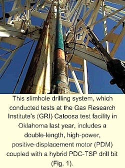
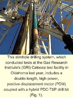
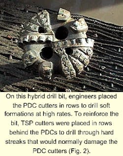
The DOE slimhole drilling system consists of a double-length, high-power, positive-displacement motor (PDM) coupled with a hybrid polycrystalline diamond compact (PDC) drill bit embedded with thermally stable diamond (TSP) cutters (Figs. 1 and 2). As confirmed by laboratory dynamometer and drilling tests conducted at the Drilling Research Center, Houston, and the Gas Research Institute's (GRI) Catoosa test facility in Oklahoma, the PDM delivered twice the torque and power of conventional motors while the hybrid bits underwent minimal wear.
Background
In the late 1950s and 1960s, more than 3,000 slimholes were drilled worldwide.1 Despite cost savings of 27-75%, however, slimholes did not gain wide acceptance due to performance problems associated with slimhole equipment such as roller bits and the misconception that large wellbores were needed for the effective completion, workover, and production of oil and gas wells.Today, advances made in PDC bit design, downhole motor, and slimhole logging tools design have resulted in renewed interest in slimhole drilling technologies.
High-power motor design
To rotate drill bits, positive-displacement mud motors (PDMs) convert hydraulic to mechanical power through the configuration of eccentric rotors in rubber stators. Thus, motor speed is proportional to flow rate and motor torque is proportional to the pressure drop across the motor.
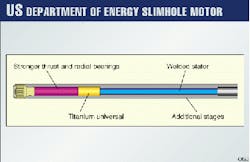
The DOE system uses a high-power slimhole motor with a double-length power section that includes twice the number of motor stages. This design doubles the motor torque and power output and allows these motors to drill twice as fast as conventional motors.
Increasing the motor power output required increasing the strength of the (Fig. 3):
- Universal joint that transmits the torque from the power section to the drill bit.
- Thrust bearings.
- Drive shaft in the motor.2
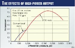
Fig. 4 shows that the 33/8-in. high-power DOE slimhole motor delivers 73 hp compared to only 28 hp for a conventional oil field motor. This high power output should increase drilling rates two to threefold when operating on drilling rigs using pumps that can deliver the higher circulating pressures required for these motors.
Hybrid bit
TSP cutters, which have the cobalt binder removed to allow them to operate at higher temperatures, are seven times more wear resistant than PDC cutters. The major limitation of TSP cutters is that they cannot drill softer formations as fast as PDC cutters because of their smaller size.
To overcome this problem, and to develop a high-power bit for use on the high-power motor, hybrid bits were developed that utilize both PDC and TSP cutters (Fig. 2). The PDC cutters are placed in rows on the bit to drill soft formations at high rates. TSP cutters are placed in rows behind the PDCs to drill through hard streaks that would normally damage the PDC cutters.
Catoosa tests
Two field tests were conducted on the high-power slimhole motors and bits at the GRI Catoosa test facility in Oklahoma, formerly operated by Amoco Corp. (OGJ, Nov. 9, 1998, p. 80). The first "shake down" test identified weak points in the design of the system while the second test compared conventional and DOE motor drilling rates.
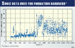
The Catoosa test site provides an ideal location for testing downhole oil field equipment under field drilling conditions because the subsurface geology provides a wide array of conditions that include both hard and soft formations. Sonic logs show that the compressive strengths of these formations range from 5,000 to 30,000 psi (Fig. 5).
During the first test, the new DOE slimhole motors drilled in the low-strength formations from 623 to 1,380 ft at rates of 100-175 fph. At 1,380 ft, the drilling crew encountered the Mississippi Lime where penetration rates dropped to 1 fph. Otherwise known as "the wall," this formation provides an excellent test interval for PDC bits as these bits typically suffer severe damage.
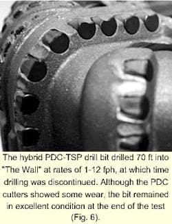
The DOE motor and hybrid PDC/TSP bit drilled 70 ft into "the wall" at rates of 1-12 fph, at which time drilling was discontinued because the test time ran out. Nevertheless, the DOE motor was still drilling effectively when the test was terminated, demonstrating that the DOE slimhole system can improve slimhole operations by effectively drilling soft and hard formations.
Although the PDC cutters showed some wear (Fig. 6), the bit remained in excellent condition at the end of the test. It was pulled only because of time constraints. Although the bit could have been rerun, it was rebuilt by rotating the worn PDC cutters to expose new wear surfaces. The TSP cutters used to backup the PDC cutters also remained in excellent condition.
At the conclusion of the test, the DOE motor was disassembled and examined for wear. The lower section of the motor stator suffered some rubber chunking as the titanium flex shaft placed too much side-load on the stator, a result of stiffness. For the second test, therefore, the damaged stator was repaired and the outer diameter of the flex shaft was reduced to make it more flexible.
Test No. 2
The second field test at Catoosa compared DOE and conventional motor drilling rates in the moderately hard Arbuckle dolomite formation from 1,605 to 2,920 ft. A conventional motor was run between two DOE slimhole motor runs. The top 800 ft of this formation is very uniform and provides an excellent benchmark to compare different drilling systems.
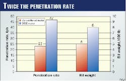
Fig. 7 shows that the DOE motor drilled 48 fph compared to 23 fph for the conventional motor. During the first DOE motor run, the drillers applied variable bit weights and encountered a hard stringer, similar in compressive strength to "the wall," near the end of the run.
For the first DOE motor run over the period of 1.75-2.75 hr, the driller applied heavy bit weights on the slimhole PDM, achieving rates as high as 50 fph. If this heavy bit weight had been used throughout the test, the high-power motor would have drilled 2-3 times faster than the conventional motor for both runs. It took approximately 1.5 hr to drill through this hard streak.
During the first part of the conventional motor run, the driller achieved an average penetration rate of 20 fph circulating at 110 gpm. After pump repairs at 1.25 hr, the flow was increased to 120 gpm and the average rate increased to 27 fph, still well below the DOE rate of 47 fph.
It was also shown on the second run that the DOE motor was able to operate at almost twice the bit weight of a conventional motor (Fig. 7), a result of the high torque output of the high-power motor, which initially achieved penetration rates of 70 fph.
It was also shown that with the commercial motor, there is a definite relationship between bit weight and the rate of penetration, as expected. With the DOE motor, however, there is no such trend. Because the same bit was used with both motors turning at 400 rpm, hole cleaning must have been the limiting factor with the DOE motor since it drilled twice as fast and generated twice as many cuttings as the conventional motor. If a by-pass nozzle had been used, and flow rate increased to improve hole cleaning, the DOE motor would have drilled even faster.
Operating characteristics
The drillers found that the DOE system was easy to run due to its high torque and high power output. With the conventional motor, however, the driller had to watch stand-pipe pressure and bit weight closely to prevent the motor from stalling. To restart the conventional motor after it stalled, the driller had to lift the motor off bottom, losing considerable drilling time.
On the other hand, the DOE motor stalled only at very high bit weights. And on the few occasions when it stalled, the driller restarted the motor by reducing bit weight slightly. It was not necessary to pick up off bottom, saving considerable time.
Post inspection
At the conclusion of the test, the two DOE high-power motors were disassembled and inspected with no significant wear apparent in the rotors or stators. The two double-length stators were inspected with a video bore scope and found to be in excellent condition, other than a minor wear point at the top of one section on the stator.
This wear point corresponded to a wear mark on the rotor, indicating that a rock must have damaged the rotor and stator.
A downhole screen will be used on future tests to prevent rocks and other debris from entering the motor. The modified titanium flex joint with the smaller outer diameter also remained in excellent condition at the end of the second test, showing that this modification worked and that side loading on the stator was no longer excessive.
Acknowledgments
The authors wish to thank Robbins & Myers Energy Systems and Griffith Oil Tool Co. for their contributions to this article.
References
- Shook, A.R., Dech, J.A., Maurer, W.C., Matson, R.P., Mueller, D.T., Hopmann, M., Boonen, P. and Reeves, S., "Slimhole Drilling and Completion Barriers," Final Report GRI-95/0182, pp. 5-6, May 1995.
- Cohen, J.H., Maurer, W.C., and Long, R.C., "Field-Testing of High-Power Slimhole Drilling System," Presented at ASME ETCE, New Orleans, Feb.14-17, 2000.
- Clark, P.E., and Shafto, G.R., "Core Drilling with SYNDAX3 PCD," Industrial Diamond Review, April 1987.
The Authors
John H. Cohen is vice-president for Maurer Engineering Inc. where he manages engineering research and development for a variety of technologies. He has 26 years of industry experience and has worked for Cameron Iron Works and Reed Tool Co.
Cohen holds a BS in engineering physics from the Colorado School of Mines and is a member of the American Society of Mechanical Engineers. He has six patents.
Curtis E. Leitko is a design manager for Maurer Engineering Inc. where he is responsible for product design logistics, conceptual layouts, manufacturing processes, and prototype testing. He has a varied educational background in computer-aided drafting and gas and arc welding. Leitko has seven patents.
Roy C. Long is currently a project manager at the US Department of Energy's National Energy Technology Laboratory (NETL). He started work in the Rocky Mountains in 1978 and eventually became an international petroleum engineering consultant.
In 1988 Long began work as principal investigator for DOE's dry drilling and coring program at Yucca Mountain, Nevada, where he managed development of the dual-wall drilling and coring system used for site investigation at DOE's proposed high level nuclear waste repository. He holds an MSc in petroleum engineering from the Colorado School of Mines.
