Difficult wells require new well control procedure
The development of new software tools and downhole sensors has led to a better understanding of dynamic conditions in the wellbore, allowing drillers to make fundamental changes in the way they approach well control.
Before these technologies became available, however, the complexity of multiphase flow forced drilling personnel largely to ignore conditions in the annulus. In its place, very simple assumptions, based solely on drill pipe pressure, had to be made.
Yet today, drilling near the "edge"-with smaller tolerances between mud weights and fracture pressures, typically prevalent in high pressure, deepwater, and underbalanced wells-no longer affords drilling professionals the luxury of discounting this information.
New technologies
This article shows how improvements in the understanding of events in the annulus can be incorporated into a simple and cost-effective, well-control program for a "more difficult" well. The example given, which compares the "new well control" and "weight and wait" methods, provides a look at a deepwater Gulf of Mexico (GOM) well drilled with synthetic-base mud.
Different variations of the new well control procedure, for example an equivalent of the "driller's" method, would be used in other circumstances. It should be noted, however, that for wells where the tolerances are sufficient, the continued use of conventional well control methods can be supported.
Two very significant improvements have occurred in drilling technologies, which can now lead to a safer, more economic operation:
- Development of fully dynamic well-control simulation software and spreadsheet front-end applications capable of modeling multiphase annular flow, real reservoir fluids, and gas dissolution in oil-base mud (OGJ, Oct. 10, 1994, p. 77).
- Combined use of pressure while drilling (PWD) and transient hydraulic-temperature models. In this case, rheologies based on downhole temperature and pressure readings can pinpoint static and circulating annulus pressures (OGJ, Aug. 22, 1994, p. 64). 2
The net effects of this new well control procedure include the following advantages:
- Greatly reduced risk for a serious well control incident.
- Improved understanding and control throughout a well control incident.
- Improved safety.
- Greatly reduced potential for lost circulation.
- Improved drilling effectiveness and reduction of overall drilling costs.
In particular, the goal for the new procedure is safely to circulate out gas without losing returns once a kick has been detected. Unfortunately, this goal is not always attainable using conventional well control methods.
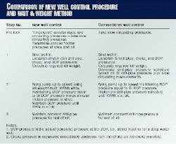
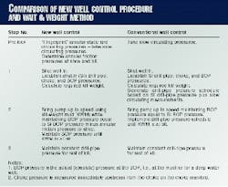
The three major differences between the new well control and conventional procedures are (see Box):
- The annular friction pressure levels established for the kill rate between the casing shoe or weak point and BOP can be backed off, resulting in less chance of breaking down the shoe.
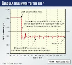
- The BOP pressure can be held constant while the kill weight mud (KWM) is circulated to the bit using a synthetic-base mud. This is far easier than following a pump-pressure schedule. It should be noted that this approach will produce a drill pipe pressure schedule which has the same shape as the conventional method.
- The choke and kill lines can be filled with a thin (light) fluid during normal drilling operations so that excessive choke and kill line friction pressures do not result at the start of the kill circulation-a result of extremely cold mud.
For both approaches, a BOP pressure gauge must be used. Other options, such as backing off the choke pressure by an amount equal to the choke-line friction pressure, or using one of the choke or kill lines as a monitor, have serious disadvantages.
In some cases there will be real-time bottomhole pressure (BHP) data available from the PWD. This will not always be the case, but if available, this information can be used during the kill circulation.
Fingerprinting
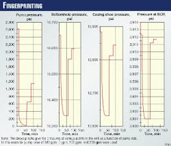
While the well is in a secure mode, an important aspect of well control includes fingerprinting, which simply means that once the shoe is drilled out, the well can be circulated at various rates while recording BHP and PWD data.
Use of a transient temperature-pressure hydraulics program allows corroboration of the PWD data and the information generated by the program, allowing for a complete pressure profile of the well to be worked out for the various circulation rates measured (Fig. 1).
Three steps are used to kill the well:
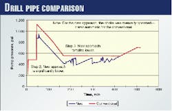
Step 1: Shut the well in and measure shut-in pressures and pit gains. The shut in uses the same procedure for both approaches; however, for the conventional kill, it is essential to construct a drill-pipe pressure schedule.
Step 2: Bring the pump up to speed and circulate the KWM to the bit.
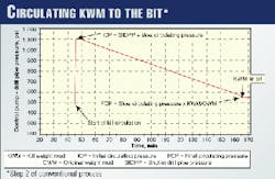
For the new well-control procedure, the BOP pressure is held constant while the KWM is circulated to the bit. For the conventional approach, the drill pipe pressure schedule is followed where the BOP pressure may be held constant while the initial drill pipe pressure schedule is attained.
Note that with the new procedure, it is possible to back off from the shut-in BOP pressure if the friction pressure of the annulus becomes significant. The goal of this action is to avoid over pressuring the annulus at the casing shoe at the start of the kill circulation.
For the new procedure, the pressure control point is shifted to the BOP and the pressures imposed upon the well (base of annulus) are controlled relative to the recorded shut-in pressures. Even if drill cuttings and other mud weight anomalies exist within the annulus, the BHPs will be maintained.
For the mud systems considered here, any gas will remain in solution unless a huge kick has taken place. Therefore, there will be no gas expansion to deal with as the influx is circulated from the bit to the casing shoe.
Applying a constant BOP pressure approach to this part of the kill affords a rational and simple method.
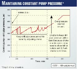
Step 3: Once the KWM reaches the bit, both methods revert to maintaining constant drill pipe pressure at a constant pump rate.
For a deepwater well, there may also be a period of overpressure applied towards the end of the kill with the KWM in the choke and kill lines. A pragmatic solution to this problem is to shut down the kill circulation, isolate the well by closing the lowermost pipe rams, and flush the choke and kill lines with KWM.
A comparison
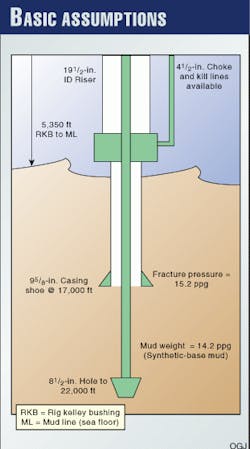
A typical GOM deepwater situation (Fig. 2) is used to compose the overall well geometry and assumptions made for the example.
Figs. 3-5 show the key control steps for both the new and conventional well control procedures.
Fig. 3, which represents the new well-control procedure, shows the controlled BOP pressure level while circulating the KWM to the bit. Note that the BOP pressure has been backed off compared to the SI BOP pressure.
Fig. 4, also representing the new well-control procedure, shows the control of the pump-drill pipe pressure once the KWM has reached the bit.
Finally, Fig. 5 shows control using a pump-pressure schedule for the conventional procedure while the KWM is pumped to the bit.
Comparing results
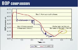
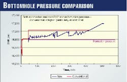
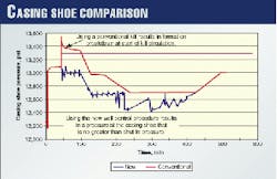
Altogether, Figs. 6-9 show a comparison of results for the two approaches where:
- Pressures within the well are generally maintained at a lower level for the new well control method, as compared with the conventional procedure.
- The pressure in the well is far better controlled at the start of the kill circulation activity with the new method, as there will be a maximum casing-shoe pressure applied to the well with the conventional method, including a greater chance of breaking the shoe down. The new procedure avoids this.
- The casing-shoe pressure resulting from the new well-control procedure is equal to or less than the shut-in pressure at the casing shoe. Thus, if the well can be shut in, it can be successfully circulated without losing circulation.
Further remarks
The approach described here is tailored for synthetic-base muds and for vertical or near vertical wells. Caution is required in its application to other well types, but variations on the type of approach shown here are possible and appropriate.
Whereas the analysis presented here is only possible because of the advanced and realistic simulation, feedback from field operations strongly supports the approach.
The question "Why is it that once I get the choke opening correct as I perform a kill, that the kill seems to go quite well with the choke left at this setting?" has been heard many times. The answer is, of course, because of the lack of gas expansion.
The key to implementing the approach described here is to build up the confidence in the underlying physics, which accurately describe gas solution behavior in synthetic-base or other drilling fluids.
This has been made more difficult by years of simplifying gas behavior as P1V1=P2V2 and the total reliance on the drill pipe side for well control.
The overall result when using the new well-control procedure is, "If you can shut the well in, you can circulate it out."
For deepwater wells in particular, this leads to a very rational overall approach as follows:
First, when just below the casing shoe and with a wide margin between pore pressure and fracture gradient, it should be possible to shut in and circulate out any reasonable kick. At this stage of the hole section, the objective should be to drill as fast as possible.
Second, at some point, it will become questionable if a "reasonable" kick can be shut in, yet alone circulated out.
At this stage of the hole section, the approach to drilling should shift from making fast hole to "tightening up" drilling practices so that if a kick occurs, the kick size will be minimized and the potential for lost circulation will be kept to a minimum.
An example of "tightening up" includes the discontinuation of drilling while weighting up the mud system thereby maintaining a more constant pit level.
Tightening up drilling practices may also help detect increasing pore pressures. The goal of drilling from this time forward is to deepen the casing point and get better shoe strength for the next hole section.
Drilling progress will be slower, but the overall gain may be significant.
Third, a greater focus is needed on pore-pressure detection where the industry is less than perfect at the moment in predicting pore pressure in front of the bit.
There is also potential for increasing the circulation rate during a kill using this method. This will obviously save time, but also reduce stress and tiredness, a leading cause of error for drilling crews.
Additionally, there are some equipment implications:
- An accurate and functioning BOP pressure gauge forms a necessary part of the system.
- It is clear from the nature of the work that there may be an advantage in introducing a semi or fully automated choke so that the BOP pressure can be maintained at exactly the right value.
- The approach described here depends on reducing operating margins, i.e., the pressure kept in excess above the formation pressure during kill operations. It is very prudent to install state-of-the-art monitoring instrumentation for detection of any problems.
- The approach noted in this article would benefit from PWD information made available at kill pump rates though it is important to have a control method not solely dependent on such data.
The authors suggest that the operators and contractors carefully assess each well and rig combination to ensure appropriate application until some general usage rules have been established with this method. The assessment of such an approach will require the most realistic well-control modeling software.
References
- Rommetveit, R., Bjorkevoll, K., and Merio, A., "Temperature and Pressure Effects on Drilling Fluid Rheology and ECD in Very Deep Wells," SPE/IADC paper 39282, Middle East Drilling Conference, Bahrain, Nov. 23-25, 1997.
- Petersen, J., and Rommetveit, R., and Tarr, B., "Kick with Lost Circulation Simulator, a Tool for Design of Complex Well Control Situations," SPE paper 49956. Asia Pacific Oil & Gas Conference and Exhibition, Perth, Oct. 12-14, 1998.
The Authors
Colin Leach is president of Well Control & Systems Design Inc. Leach attended Cambridge University where he earned Bachelors and Masters degrees in chemical engineering. He holds three patents.
Dave Schwartz is a consultant in unique well-control problems and deepwater drilling design. Formerly with Conoco Inc., he held the positions of drilling manager in London and Stavanger, manager of well systems for the Hutton Tension Leg Platform, manager of drilling and completion technology, and manager of marine and arctic technology. Schwartz holds a BS in petroleum engineering from the University of Pittsburgh and was also an employee of Martin-Decker Totco.
