Modifications solve desulfurization unit start-up problems
After a difficult, extended start-up, modifications to equipment, procedures, and chemistry by MOL Hungarian Oil & Gas Co., Budapest, to its gas plant at the Szeged production unit in southern Hungary have permitted the LO-CAT II unit to operate close to expectations.
The experience exemplifies the challenges of using aqueous, liquid-redox desulfurization technology for direct treatment of sour associated and process gas streams at elevated operating pressures and relatively high CO2 partial pressures.
Installation
ARI Technologies, developer of the LO-CAT and LO-CAT II processes (and predecessor of USFilter/Gas Technology Products) supplied a LO-CAT II desulfurization system to MOL Hungarian Oil & Gas Co. for operation at the Szeged production unit, approximately 150 km southeast of Budapest. This unit was designed to treat gas at elevated pressure.
Furnished at the same time by others were auxiliary operations such as the water-removal system downstream of LO-CAT.
Although the LO-CAT II unit was designed to treat natural gas, the actual gas is a blend of recycled process gas and associated gas collected from the oil fields around the plant. Both oil and gas from the oil fields are simultaneously transported to the plant via a mixed-phase pipeline, followed by separation in a bank of gas-liquid separators.
After the separators, the associated gas is combined with the recycled process-gas stream, compressed to 16-18 barg and then sent to the LO-CAT II unit.
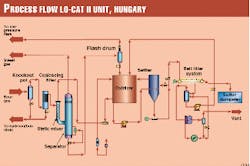
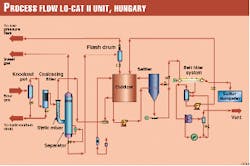
Fig. 1 presents the flow diagram of the LO-CAT II unit.
As the design team anticipated some liquid entrainment in the sour gas, the first two unit operations are a knockout pot and a coalescing filter. The knockout pot had a liquid-surge volume of 1 cu m.
After the coalescing filter, the sour gas is routed to the LO-CAT II static mixer absorbers where it is contacted with oxidized LOCAT catalyst solution. (Two static mixers were provided with the forethought that they would probably plug with sulfur and would therefore require periodic cleaning).
Exiting the static mixer absorber is a two-phase stream consisting of sweet gas and reduced LO-CAT solution, which then enters the absorber separator. In the separator, the gas and liquid are allowed to separate.
The treated gas exits the LO-CAT II unit after passing through a mist eliminator. Downstream of the unit, the gas is then cooled to remove water, then compressed to 64 barg (approximately 930 psig) in the third-stage compressor.
The reduced LO-CAT solution from the separator passes through a pressure-reducing valve and flash drum, then gravity drains to the oxidizer, where the iron is regenerated for re-use in the absorber.
A slipstream of this oxidized solution is then sent to the settler where sulfur is allowed to settle and subsequently transferred as slurry to the belt filter. Filtrate from the filter is returned to the oxidizer, while sulfur cake is discharged after washing. A small quantity of flash gas is vented to the flare header.
Chemistry
The LO-CAT II process utilizes a ferric (Fe+3)-ferrous (Fe+2) amino-carboxylate redox couple as a catalyst to absorb H2 from sour gas and to oxidize it to elemental sulfur in the absorber, according to Reactions 1 through 3. (See accompanying box.)
The ferrous ion that is produced is then recycled to the oxidizer where it is regenerated by oxygen according to Reactions 4 and 5.
The overall reaction, therefore, is shown in Reaction 6. This reaction is the overall Claus reaction; it can be seen that the role of iron is catalytic, as it is not consumed.
Chelating agents (L in the reactions), although not partaking in any role in the reactions, maintain the ferric and ferrous ions in solution.
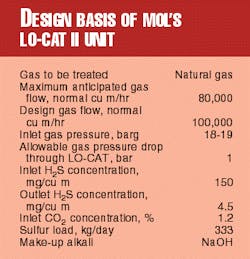
The LO-CAT II unit was designed as outlined in Table 1.
Start-up
During initial start-up and subsequent restarts of the unit, problems arose in several areas that required modifications to equipment, procedures, and chemistry.
- Liquid entrainment in sweet gas. During initial start-up, excessive liquid entrainment occurred whenever the sour-gas flow exceeded 60,000 normal cu m/hr. At that time, this was attributed to the absorber separator vessel being undersized.
As a result, not only was it difficult for the gas and liquid to separate, but sulfur particles were also entrained. The demister fouled as a result and further aggravated the entrainment problem.
As a remedy, the separator was resized and a new separator, complete with modified mist eliminator, was retrofitted into the plant. As a result, gas flow up to 80,000 normal cu m/hr was achieved without liquid entrainment.
- Foaming; floating sulfur. Foaming and floating sulfur are typical start-up problems that often are remedied in short order. Such was not the case with this unit, however.
Foaming and sulfur-settling problems usually go hand-in-hand and are a result of condensed hydrocarbons or an imbalance in the use of surfactant and anti-foam additives.
When condensed hydrocarbons are present, sulfur particles become coated. These hydrocarbon-coated particles cannot be wetted and can trap air or gas bubbles so that they float on free liquid surfaces such as in the absorber separator, oxidizer, and settler, and therefore cannot be removed from the system via settling.
When surfactant is added in an attempt to wet the sulfur, foam can be created. Further, adding antifoam can actually aggravate the foaming situation.
Eventually, it was determined that there were excessive liquid hydrocarbons entering the LOCAT II unit. At one point, a sample of solution was found to contain solid wax-like material. Additionally, stable emulsions were forming among the aqueous LO-CAT solution, sulfur particles, and hydrocarbon condensate.
In retrospect, hydrocarbon-induced foaming may have aggravated the entrainment situation in the absorber separator as well.
If the condensate could have been prevented from entering the system, this entire problem would not have existed. It was determined, however, that considerable condensate was frequently being introduced from both the process gas and as a result of operation of the two-phase oil-gas pipeline.
Consequently, it was deemed impossible easily to keep the condensate out. Therefore, a multifaceted approach to the problem was undertaken.
To reduce the quantity of condensate and to provide immediate, short-term relief, modifications were made to the sour-gas transfer line to allow condensate to be trapped out.
Fortunately, the main line was high on the pipe rack and a simple drainage boot could be retrofitted to catch the condensate. In addition, the original knockout pot was replaced with a larger one.
At the same time, MOL's research and development group developed a new additive, which would allow the stable emulsions to be broken and the sulfur to be wetted.
Their goal was met by the formulation of what is termed "B-3," which has replaced ARI-600 and anti-foam in this unit and has allowed the plant to operate in spite of continued hydrocarbon influx.
- Chronic pump failure. The catalyst recirculation pump in this plant was a six-stage, progressive-cavity pump originally selected because it best fit the hydraulic specifications and had operated successfully in many previous units, but at lower pressure.
During the several attempts to start the plant, however, it became apparent that this pump would be undependable in the long-term, even though a larger, slower-running pump was installed as recommended by the manufacturer.
As a result of the failure of the larger pump on Christmas Eve 1997 and the need to keep the plant running, plant maintenance personnel retrofitted a scavenged multistage centrifugal pump. This style pump had never been used in LO-CAT units before because of fears of erosion and interstage plugging. But there were no options available on Christmas Eve.
A year later, this pump was still operating, but the capacity of the unit had been compromised, as the volumetric capacity of this pump was less than required.
As a result, in December 1998, a new pump with the required capacity was installed. Encouraged by the lack of erosion and interstage plugging in the multistage pump but fearing interstage plugging in the long-term, MOL selected a Durco, Mark III pump.
This pump is centrifugal with an open impeller and operates at 3,160 rpm. So far, the new pump has performed satisfactorily, having operated successfully for 15 months.
- High pressure drop. Absorber fouling and backpressure in the water-removal train downstream of the LO-CAT unit caused high system pressure drop. Because absorber plugging had been expected, the two static mixers were furnished with flushing connections.
Unfortunately, the planned cleaning procedure was ineffective, possibly due to the stickiness of hydrocarbon-coated sulfur. Operators implemented an alternate cleaning procedure, using steam, but the pressure drop was never reduced to the as-clean condition.
In September 1998, a revised steaming procedure was implemented that allowed recovery to the as-clean condition. Implementing this procedure, however, required the absorber to be isolated by blinds because the original isolation valves were not rated for steam service.
These valves have been replaced, which allowed more frequent steam outs, lower pressure drops, and increased gas throughputs.
Modifications to the water-separation train downstream of LO-CAT are also planned for the future and will permit a further increase in gas flow.
- Poor H2-removal efficiency. From the onset, H2-removal efficiency had been less than designed for, due largely to the CO2 concentration of the sour gas being higher than the design, thus greatly reducing the solution pH at the discharge of the static mixer (where liquid and gas emerge as a two-phase stream).
As a remedy, additional solution buffering (that is, more bicarbonate ion) was required. Unfortunately, increasing the buffer when NaOH is used as alka* supply can cause precipitation of NaHCO3. Usually, KOH is used for higher buffering capacity but it is more expensive.
Operators at MOL decided to supplement the NaOH feed with NH4OH. This worked insofar as the solution buffer capacity was increased, but there was a continuous NH3 loss from the oxidizer vent.
A packed column scrubber was added to the vent, using oxidizer make-up water as the absorbent, which had some benefit. But ammonia losses continued.
Further, a review of solution chemistry in September 1998 revealed that the solubility product of NaHCO3 was being approached. This prompted a switch to KOH and the discontinuance of NH4OH in December 1998.
With improvement in buffer capacity, H2-removal efficiency improved to about 90-95% but remained less than design gas flow because of high system pressure drop.
- Corrosion problems. In summer 1996, discovery of severe corrosion in the oxidizer vessel led to its replacement.
In September 1998, inspection of the oxidizer revealed no corrosion on the vessel body, but corrosion was noted on the top exterior of the originally supplied internal piping.
The corrosion was of tunneling nature, indicative of microbial-induced corrosion (MIC) that can take place beneath sulfur deposits, especially if the system is out of service for an extended time and may become anaerobic. This had been the situation for the first few years of this unit's existence.
Since the corrosion had not passed through the pipe wall and operating pressure was low, it was decided not to replace the piping.
The same inspection revealed that the oxidizer air sparger sleeves, made of EPDM rubber, were severely embrittled and cracked. At the time, they were replaced with identical sleeves, but a review of literature and thorough compatibility tests determined that EPDM was susceptible to attack by aliphatic hydrocarbons, present in this plant in large quantity.
At present, additional laboratory tests are being conducted with polyurethane sleeves, which promise to have greater resistance to hydrocarbons.
Present situation
The plant has been operating with a gas flow of 60,000-100,000 normal cu m/hr, averaging about 65,000 normal cu m/hr, with a sulfur load of about 50 kg/day (due to low H2 concentration in the gas).
The improvements made in the hydrocarbon collection system, coupled with improvements in operating procedures, have reduced the ingress of condensates into the unit.
In turn, this has reduced difficulties associated with floating sulfur, foaming, and absorber fouling. The development of B-3 has further improved hydrocarbon-induced problems.
The recently replaced recirculation pump, the switch to KOH, and improved absorber-cleaning procedures have permitted higher gas flow (100,000 normal cu m/hr when clean) and greater H2-removal efficiency (averaging 90%).
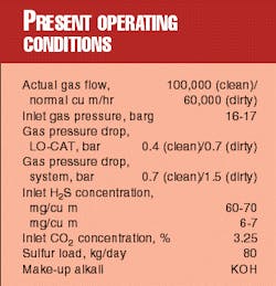
Table 2 summarizes the present operating conditions of the unit.
Corrosion is not considered to be a problem at this time, but an inspection of the oxidizer and settler is planned during the next turnaround. Replacement of the EPDM sleeves by polyurethane is a possibility at that time as well.
MOL anticipates that when final modifications to the water-separation train are made, a sustained gas flow of 100,000 normal cu m/hr, meeting pipeline H2 specification of less than 4.5 mg/cu m will be achieved (static mixer efficiency improves with increased gas flow). Table 3 summarizes the anticipated future conditions.
The experiences gained in this first LO-CAT II elevated-pressure application, a subsequent 4 long ton/day unit operating at 30 barg, and a high pressure pilot plant operating at nearly 70 barg have been invaluable and will serve as a guide to the design and operation of future units of this nature.
The Authors
Myron Reicher is manager of process technology for USFilter's gas technology products group, Schaumburg, Ill. He has been with this group and its predecessor, ARI Technologies, for 9 years and previously held positions of chief engineer and product development manager in ARI's LO-CAT group. Previously, he was a process engineer at Hooker Chemicals and a production superintendent at Olin Chemicals, both in Niagara Falls, NY, and at Akzo Chemicals, Chicago.
Bill Niemiec is manager of technical services for USFilter's Vivendi Corp. He has held various positions over a 10-year period with Wheelabrator Technologies and Chemical Waster Management. Niemiec holds a BS in chemical engineering from Northwestern University, Chicago, and an MBA from Northern Illinois University, Dekalb.
Tamas Katona he has been working since 1996 as production manager of MOL Hungarian Gas and Oil Co. gas-processing plant at Szeged. In 1995, he became head of the laboratory at the Szeged unit. Between 1990 and 1992, he was a visiting scientist in chemistry at the University of California Berkeley. Between 1992 and 1995, he continued research at the department of organic chemistry of JATE University, Szeged, Hungary, as a senior researcher. Katona graduated in 1987 from JATE University and conducted post-graduate studies in organic chemistry. He is member of the committees of catalysis and of hydrocarbon processing of the Hungarian Academy of Sciences.


