Lower costs, environmental protection drive future pipeline technologies
Constructing oil and gas pipelines onshore and offshore in the 21st Century will reflect efforts well underway at the end of the 20th Century: developing more cost-effective technologies but also mitigating environmental impact during construction and operation. These efforts will improve public acceptance of such projects.
This discussion follows the path that implementation of a typical pipeline project normally follows, from route selection via basic and detail engineering through to construction, operation, and maintenance of the system.
Onshore
Route engineering
Great advances in surveying and mapping have been evident in route engineering in recent decades. But such development has also been characterized by a fundamental change in selecting the optimum route, which had been based formerly on technical and economic considerations.
Today-and especially in the coming decades-it is necessary to find a route which is technically feasible, is constructible at reasonable costs, causes minimum damage to the environment, and creates minimum resistance from the public, and for which the necessary right-of-way can be acquired without delays.
These changes in approach for route selection and in definition of the "optimum route" are not restricted to urban, industrialized regions, but also apply to developing countries.
Although technical aspects of the general route are still studied with existing maps, there is a strong preference for use of satellite images.
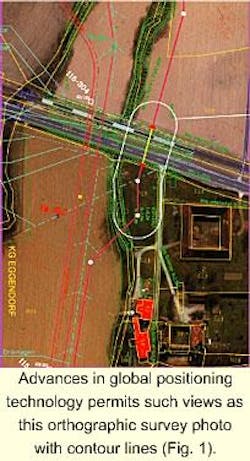
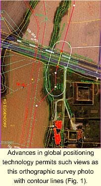
For detailed route investigation, it is state of the art to take advantage of the progress made in aerial survey. Orthographic photos from this survey in combination with contour lines make possible in-depth route studies without field work. Only as a last step is the route verified in the field.
Aerial photos or videos also help define the environmental status as part of an impact assessment and give opportunities for fast and cost effective mapping of the topographical and environmental situation.
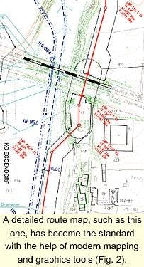
Depending on the grade of required detail, accuracy can be adjusted by the height of the GPS-controlled flight for the photo shooting and the implementation of conventional surveyed data for special points (GPS = global positioning system). Figs. 1 and 2 offer examples.
The future lies in satellite-based surveys, but as yet the accuracy of publicly available data is insufficient for detailed engineering. Resolutions of satellite imaging are constantly improving, however.
Modern information technology in the form of geographic information systems (GIS) has revolutionized pipeline mapping. The layers of topographic, environmental, pipeline, and ROW-related data can be combined in various ways to produce all necessary maps and alignment sheets.
Modern GIS technology facilitates not only production of the route drawings, but also any revisions due to relocations to find the optimum route as defined above.
Still unsolved is the search for a similar, cost-effective method for conducting soil surveys. Research and development concentrate on infrared- or radar-based surveys, but the relevant data still are limited to the upper zones. Development of seismic surveys for this specific purpose might be a feasible solution.
Pipeline design
Driven by the desire to minimize investment for pipelines, efforts are being made to increase operating pressures in combination with development of higher steel grades and to reconsider installed spare capacity in pumping and compressor stations. A typical example of this trend is the Alliance Pipeline with 120-bar (1,740-psi) operating pressure and single unit design.1
Operating costs have been reduced by considerably improving the thermal efficiency of gas-turbine drives especially for gas pipelines and installation of high-efficiency pumps combined with variable-speed drives for crude oil and product pipelines.
Application of modern information technology has revolutionized monitoring and control of pipeline systems. Modern hard- and software that runs pipelines on-line or assists the operator off-line aims at safe and cost effective operation.
Fiber optic cable laid along pipelines is used for data transmission and for sensing, opening up a wide variety of new applications especially for prevention and detection of leaks.2
Driven by environmental considerations, efforts have increased for primary safety (keeping the pipeline tight, no leaks) and secondary safety (fast detection of and response to a leak).
In primary safety, advances have been made to develop steel with higher resistance against the effects of corrosion and aging. Despite progress, internal corrosion in oil field lines and crude oil pipelines remains unresolved.3
Modern supervisory control and data acquisition (scada) systems can detect leaks even under transient flow conditions and locate leaks with satisfactory accuracy. Cost-effective ultrasonic flow metering supports this development.
Results of environmental impact and quantitative risk-assessment studies can be fed into a GIS-based pipeline information system to provide a computer-based emergency response plan.
The combination of such a plan with modern leak detection and locating system is a major improvement and represents the highest achievable standard for secondary safety of a pipeline.
Efforts have also been made to reduce emissions of pipeline installations during normal operation by development of high efficiency dry low-emission (DLE) gas turbines, by improving the seal mechanism of floating roof tanks by using instrument air instead of instrument gas, and by reducing the effect of oil spills in stations.
Materials
The range of materials available for pipeline application has grown significantly, with a trend toward higher strength steel grades.
This development started more than 25 years ago along with introduction of thermo-mechanical rolling practices.
In the early 1970s, Grade X-70 was introduced for the first time for use as line pipe in the construction of gas transmission pipelines. Since then, X-70 material has proven reliable in numerous pipeline projects. The material has been optimized in the course of further development of thermo-mechanical rolling and can be welded trouble-free with cellulosic electrodes.
Following satisfactory experience gained with X-70, Grade X-80 line pipe came into use for the first time in 1985 on a trial basis. From beginning to the 1990s, nearly all big gas high-pressure pipelines have been built in X-80.
For large-diameter oil pipelines, the tendency towards higher-yield steel has been slightly delayed because actual technical rules did not recognize steel higher than Grade X-52 and therefore required special approval for high-yield steel.
In addition, requirements concerning crack elongation were higher for oil pipeline than for gas pipelines because of unsteady state flow conditions.
Since beginning of the 1990s, X-70 steel can fulfill all requirements that X-52 pipe does. For the first time, this steel grade was used for a long-distance crude oil pipeline in 1994.4
Even today, it is possible to lay Grade X-100 line pipe and maintain safety-related criteria.
In addition to pipe material, statistical parameters used by new reliability-based codes have improved manufacturing reliability.
The clear requirement is that the weld shall not be a weak part of the pipe. The welding factor therefore shall be at least 1.0. This is necessary because the finished pipeline must be subject to high-pressure hydrostatic tests (stress-tests) in which the base material will be tested at pressures equivalent to up to 110% of the specified minimum yield strength (SMYS).
Submerged arc welding (SAW) is still considered the qualitatively best solution for pipe production. The weld metal has a high Mn content and is alloyed with Mo. This results in a good compromise between toughness and mechanical strength.
High impact values of 100-200 Joules/cu cm are reached. Normally flattened transverse-weld specimens are breaking in the base material, that is, outside of the weld region.
High-resistance external coatings have significantly decreased the risk of external corrosion. In addition, the electrical resistance of the three-layer polyethylene coatings used today are by far better than that of bitumen coatings of 30 years ago. This has the advantage of very low current demands in the CP system.
On the other hand, it has the small disadvantage that over-voltage in the pipeline, for instance from lightning, is not dropped into the earth but transported through the pipeline and may affect installations far away from the lightning.
Construction
Increased environmental protection requirements have contributed also to a change in construction practice. It is common in a number of countries for representatives of the relevant authorities to be present during construction, at least at sensitive sites.
For all impacts that cannot be mitigated (for example, erection of stations and the relevant soil sealing), compensation measures have to be implemented on suitable sites.
These measures must be defined during planning and depend on the severity of impact. In addition, the pipeline route must be monitored regarding the status of the affected environment after construction is completed.
Major improvements in timely and cost-effective trench opening have been made by substituting heavy rock trenching machines for conventional blasting of rocky sections.
Invention of directional horizontal drilling for the landfall sections of marine pipelines or crossings with other infrastructure, rivers, for example, was also a major accomplishment.
Installation time was significantly reduced over the conventional method, and casing pipe installed using this process has little or no effect upon the beach environment. The system is properly protected against exposure to wave or storm action.
The use of mechanized or automatic welding equipment has yet to penetrate the market significantly, but for large diameters and heavy-wall pipes, this technology is economic compared with conventional manual welding. Major advantages include consistent weld quality, higher production rates, and avoidance of delayed hydrogen cracking due to the inherent low-hydrogen process.
Such non-destructive testing technologies as radiography, ultrasonic testing, magnetic or liquid penetrate testing have contributed greatly to the increased reliability of pipeline construction.
The technique that advanced most in recent years is mechanized ultrasonic testing. Especially in combination with mechanized welding, it offers such advantages as fast and detailed inspection, documented electronically processable results, and no emissions during testing.
Operation, maintenance
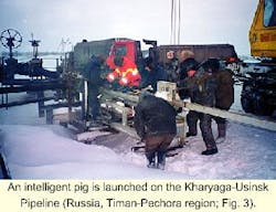
Another major improvement was introduction of the instrumented in-line inspection vehicle ("intelligent pig") as a highly reliable tool for internal inspection of a pipeline system. The available applications range from geometric and metal-loss inspections via leak and crack detection and location to GIS-based pipeline location surveys.
Similar to the general tendency in information technology, the recording capacity of these tools is constantly improving.
Moreover, GIS-based emergency-response plans enable operators to react promptly to a pipeline failure. Sophisticated response-plan software analyzes all eventual scenarios (leak volume, environmental impact, specifically sensitive areas) and defines the relevant actions to be taken in advance.
Operational improvements were evident when, in 1978, the Trans-Alaska Pipe Line System initiated development of flow improvers (drag reducing agents) for commercial use in hydrocarbon pipeline systems.
Since then, application of flow improvers has become common for relieving and managing temporary capacity bottlenecks or reducing operating pressures at sensitive sections.
On the risk-assessment front, pipeline operators face increased costs for maintenance, reduced reliability, and the risk of leakage due to degradation.
Preventive maintenance, regular inspection, and rehabilitation based on such inspection reduces risk of leakage and helps quantify an acceptable failure probability.5 Costs incurred for regular maintenance, however, increase with over time and can become significant, especially when maintenance is based on fixed, regular schedules.
Risk-based maintenance concepts and subsequent optimized rehabilitation approaches instead of system replacement aim at prolonging system life at minimum cost.6
Fig. 3 shows the successful inspection run on a "non-pigable" field line in northern Russia.
Offshore
Development of offshore pipeline technology has been largely driven by either the desire to develop new fields that are hotter, deeper, and in more hostile environments or the need to reduce costs.
The following describes offshore pipeline technology advances in design, materials, construction, deepwater, and high temperature-high pressures (HT-HP) operations.
Design
Pipeline engineers have worked to develop new codes and more accurate methods for predicting pipeline behavior.
Predicting flow regime within a pipeline is key in a successful design. Slugging, hydrates, and waxing can all lead to reduced production or costly maintenance. The industry has invested heavily in such joint industry projects as Deepstar in the US and Multiphase in Europe to understand of flow better.
Multi phase-prediction software, such as OLGA and PLAC, addresses certain flow regimes but further development continues for pipe-in pipe systems and long distance tie-backs.
The Britannia project was the first offshore project to use the results of the Norwegian joint industry project SUPERB to justify an increased design factor for wall-thickness design to UK safety regulating agency Health and Safety Executive.
Also, in the past 2 decades, significant effort has gone into more accurate prediction methods for pipeline collapse. Although there is general agreement on the behavior of relatively thin-walled pipes for moderate deepwater conditions, significant discrepancies have arisen for thicker walled pipes that are necessary for ultra-deep water.
A growing body of information has been recently supplemented by results from full-scale tests and new prediction methods developed for the proposed Oman-India Pipeline across the Arabian Sea, the route whose water depths reach 3,500 m.7
Prevailing seabed environmental conditions drive required submerged weight of the pipeline. Dynamic on-bottom stability software such as AGA and SIMULATOR have been used to reduce the submerged weight of pipelines by allowing pipelines to move within specified corridors.8 9
The Hyde project in the Southern North Sea used plastic fins attached to the pipeline to promote self burial and eliminate the need for trenching.
Spanning of deepwater pipelines risks local buckling from combined bending and external pressure after pipelay. This requirement drives the need for accurate survey data and possible seabed intervention work or re-routing prior to pipelay. If the seabed is very rough, then interactive touchdown monitoring and pipelay can reduce span-rectification costs.
This technique was used during the Straits of Gibraltar project significantly to reduce the rock-dump span correction. The Asgard project made use of strain-based acceptance criteria and advanced three-dimensional (3D) seabed span analysis to reduce rock-dump quantities along the export pipeline route as it crossed an area of iceberg scarring.
Pipelines can be subject to loadings as the result of mudslides or turbidity currents. Mudslides produce higher loadings on pipelines than turbidity currents.
Typical locations for mudslides are in the sediment-drop zone of large rivers and along the edges of continental shelves. The Malampaya project has developed methods to assess these loadings and establish the need to re-route the pipeline.
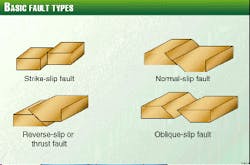
Fig. 4 depicts basic fault types. Finite-element programs such as SIMULATOR have been developed to assess the impact of these types of loading on pipelines.10
Work to date indicates that pipelines on the seabed can survive quite severe fault movements.
Recent trends in design approach have been towards limit-state and reliability-based design methods.11-15 Such approaches are now being applied to pipeline design. The Shell Malampaya project, for example, encountered water depths of more than 900 m and is applying the newly published DnV 96 limit-state design criteria.16
These methods are likely to be the way forward in ultra deepwater pipeline design and indeed may be the only means of achieving a feasible design in some cases.
ISO, DnV, and API have all updated their codes to take advantage of developments in limit state design and use of structural reliability analysis.
Materials
At the start of the 1980s, Grade X-52 linepipe was the norm for offshore pipe; now in the 1990s Grade X-70 is common and Grade X-100 is being evaluated. In addition to pipe material, statistical parameters used by new reliability-based codes have improved manufacture reliability.
Internal corrosion is a major source of failures of small-diameter flowlines carrying unprocessed product from subsea wells. The Thames project was the first to use metallurgically bonded clad pipe subsea in the early 1980s.
Solid duplex flowlines were commonly specified in the 1980s and early 1990s, but the cost is high. Statoil championed use of 13% chrome on the Asgard flowlines.
Mechanically bonded pipe has been developed as a low cost alternative to metallurgically bonded clad pipe and was used successfully on the Elgin-Franklin project.
Construction
The last 2 decades have seen new installation vessels being developed to challenge the traditional third-generation laybarge with anchor spread .
In the traditional S-lay configuration, Allseas introduced Loralay in the late 1980s to compete for the flowline market. Allseas then developed Solitaire in the late 1990s to compete for the large-diameter trunkline market.
Coflexip Stena Offshore operates the reelship Apache and, with Kitt, is extending reel technology to larger-diameter pipe and mounting the reel on a vessel large enough to support a vertical stinger.
Horizon Offshore and DSND Subsea Ltd. are building Millennium, capable of installing 16-in. pipe in 2,400-m water. Stolt Comex Seaway's Seaway Falcon can install 12-in. pipe in 1,000-m water.
J-lay was seen as the solution to ultra deepwater installation and has been utilized for some time, mostly in the reel-lay configuration and for relatively small diameter pipes.
Heerema installed the Maui pipelines with a J-lay package mounted on the Balder. McDermott has a J-lay package mounted on the DB50 that has been used to install a several pipelines up to 18-in. OD in the Gulf of Mexico.
Saipem has developed a J-lay module for its 7000 and are testing it for use on the Blue Stream project to install 24-in. pipe in 2,100 m water (OGJ, Sept. 6, 1999, p. 52).
Development of deepwater production and transportation facilities is contingent on the ability to construct pipelines and flowlines in ever-increasing water depths that present such new challenges as severe seabed and environmental conditions.
In terms of water depths in which pipelines have been installed to date, it is necessary to distinguish between the function and size of the pipelines. Smaller diameter, usually in-field flowlines of less than 14-in. OD, have been installed in water depths in excess of 1,500 m.
For example, Allseas installed the 12-in. Mensa pipeline to 1,615 m in the Gulf of Mexico in 1997. Coflexip Stena Offshore has installed rigid flowlines for Petrobras in 1,373 m in the Campos Basin (Marlim Field) offshore Brazil and holds the current deepwater production record of 1,709 m for flexible flowlines.
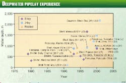
Fig. 5 shows the increase in water depth in which pipelines has been installed.
The 1990s have seen the product temperatures of some fields increase from 60 to 160° C. Such fields as Mallard, Erskine, Elgin, and Jade have had to develop flowline designs capable of operating at these temperatures.17 Such methods as strain-based design and snake lay have been developed in order to make these projects feasible.
References
- Janzen, T., and Horner, N. W., "The Alliance Pipeline - a design shift in long distance gas transmission," International Pipeline Conference, Calgary, June 9-11, 1998.
- Hausmann, A., "The usage of fibre optic cables as distributed fibre optic temperature sensors," unpublished manuscript, 1999.
- Performance of cross-country oil pipelines in Western Europe - statistical summary of reported spillages, CONCAWE, Brussels, 1996.
- Sinagl, A., Volv, V., Feizlmayr, A.H., and Kohler, A., "The Middle European Crude Oil Pipeline (MERO)," Erdöl Erdgas Kohle, Issue 3, 1995.
- Feizlmayr, A.H., Fassl, H., "Inspection and Rehabilitation of crude oil pipelines in the FSU and Eastern Europe", MIOGE, Moscow, June 1998.
- Feizlmayr, A.H., Weil F., "The economic competitiveness of crude oil pipeline transport over long distances," International Pipeline Conference, Calgary, June 9-11, 1998.
- Tam, C., et al., "Oman-India Pipeline: Development of Design Methods for Hydrostatic Collapse in Deep Water," Offshore Pipeline Technology Conference, Amsterdam, Feb. 15-16, 1996.
- de Norske Veritas, "On Bottom Stability Design of Submarine Pipelines," RP E305, October 1988.
- Rabian, E., et al, "Subsea Pipeline Response to Seabed Movement Due to Faulting," OPT99, February 1999, Amsterdam.
- McKinnon, C., et al, "A Case Study of the Britannia Gas Export Pipeline," Offshore Pipeline Technology Conference, Amsterdam, February 1997.
- McKinnon, C., and Ellinas, Charles. Reliability Based Limit State Methods Applied to Upheaval Buckling," Risk Based and Limit State Design and Operation of Pipelines, Aberdeen, October 1998.
- Hauch, S., et al, "Use of Finite Element Analysis for Local Buckling Design of Pipelines," OMAE 98, Lisbon, July 1998.
- Bai, Y., et al, "Wave Induced Fatigue of Free Spanning Pipelines," OMAE 98, Lisbon, July 1998.
- Bai, Y., et al, "Reliability Based Limit-State Design and Requalification of Pipelines," OMAE 98, Lisbon, July 1998.
- det Norsk Veritas, "Rules for Submarine Pipelines," December 1996.
- Preston, R., et al, "Controlled lateral buckling of large diameter submarine pipelines by snaked lay configuration." ISOPE, Brest, France, June 1999.
The Authors
Adolf H. Feizlmayr is partner and managing director of ILF Consulting Engineers, Munich. He holds a MS in petroleum engineering from the University of Leoben (1961) and has more than 35 years' international experience in the oil and gas sector.
Colin McKinnon is a technical director of JP Kenny, London. He has 20 years' experience in engineering related to offshore pipelines and subsea systems in projects in Europe, America, and Asia.
