Reducing scale, increasing flexibility are targets of new LNG designs
Recent years have seen advancement of several transportation schemes aimed at making natural gas production from smaller and remote or scattered offshore fields more economic.
For the most part, these efforts have focused on liquefaction in an attempt to reduce the scale and increase the flexibility of liquefying natural gas.
The traditional LNG scheme, the "LNG chain"-liquefaction, transportation, and regasification-has been so capital intensive that linking major reserves (in Indonesia or Qatar, for examples) with large markets (Japan or Europe, for examples) under 20+ year contracts has been the only way to make the economics work (OGJ, June 2, 1997, p. 54).
The distances involved generally preclude a dedicated pipeline movement in favor of one or more dedicated LNG tankers.
Amos Avidan, manager of surface engineering for Mobil Technology Co., Dallas, says that traditionally, LNG reserves of about 1 tcf/1 million tonnes/year (tpy) of LNG sales have been needed to satisfy the standard 20+ year LNG contracts.
Recent proposals have generally aimed at breaking that expensive chain, or at least making it more flexible in being able to serve scattered, individually smaller supply aggregations and smaller but growing markets.
A handful of proposals, none yet commercially employed, seek to reduce the scale of the liquefaction step and make it more mobile. The major designs call for LNG plants on ship, barge, or gravity base structure (GBS).
The idea is very simple: The floating LNG plant functions as something of a "mobile aggregator," moving among smaller, disparate offshore gas fields so as to preclude or at least reduce expensive, fixed subsea gathering systems and production platforms.
Avidan says that since an offshore LNG plant, floating or gravity based, can be moved, it may be used to develop a smaller gas reserve, limited only by deliverability.
Floating liquefaction
Most of the benefits of offshore LNG production, says Avidan, come from savings in offshore infrastructure (platforms, pipelines ashore) and elimination of harbor facilities: "These potential savings are site-specific."
The safety and reliability of offshore LNG production, he says, can be demonstrated successfully, and "it is possible that commercial application of offshore LNG production will indeed become a reality in the 21st Century."
He says that some areas of the world that have been mentioned as particularly attractive for offshore LNG production are offshore Australia and West Africa.
But smaller-scale LNG systems, primarily for offshore ship, barge, or GBS platform, cannot simply consist of a base-load design that has been shrunk. Very quickly, the economics of such a strategy are defeated by all but the highest sales-gas prices.
That's the opinion of Brian C. Price and Robert A. Mortko of Black & Veatch Pritchard Inc., Overland Park, Kan. New ideas are needed based on "low capital cost concepts and an acceptance of a reduced level of redundancy in the design."1
They have advanced Black & Veatch Pritchard's Prico II process, a single mixed-refrigerant consisting of nitrogen and light hydrocarbons from methane to isopentane.
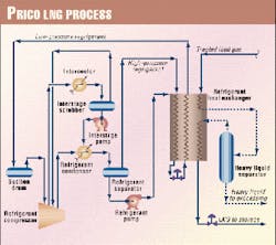
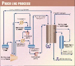
The basic flow scheme (Fig. 1) is the same regardless of the size of the liquefaction unit. Process units have been designed from 10 MMscfd to more than 1 bcfd of feed gas. "Only the size and configuration of the compression and refrigerant exchanger are different for the various size units," say Price and Mortko.
The need of floating LNG systems for compact process designs to conserve deck space is well served by the modular nature of the Prico process, they say. The main heat exchanger occupies a low profile in the process, which also carries a low equipment count. Moreover, "no pure component refrigerants are involved in the process, which leads to a small inventory of refrigerant components."
For a ship-mounted LNG process system, Price and Mortko note that a typical vessel of 300 m by 60 m can handle liquefaction of 1.5-3.0 million tpy. Complicating shipboard LNG production is the need to accommodate associated condensate production, resulting in a storage requirement for up to 200,000 cu m of LNG and up to 150,000 cu m of condensate.
The concept of floating liquefaction has already advanced beyond the mere design stage.
Earlier this year, Paragon Engineering Services Inc., Houston, announced that a joint industry study had led to development of new technology to produce LNG from remote fields using floating production, storage and offloading (FPSO) vessels.
The project was led by Chevron Petroleum Technology Co. and included participation from Amoco Production Co., VICO Enterprises Inc., Gaz de France, Woodside Energy Ltd., Conoco, Inc., BP Exploration, Statoil, BG Technology, and Shell Deepwater.
IHI and Bouygues Offshore (BOS) worked as subcontractors to Kellogg Brown & Root, providing vessel and LNG containment tank conceptual designs, said Paragon. IHI developed a steel hull design; BOS provided a concrete hull design.
ABS Americas provided expertise on statutory and regulatory guidelines for the construction of the FPSO.
The FPSO may be a viable alternative for some remote offshore gas field developments, according to Paragon representative Richard Hill. An FPSO-based LNG plant can also eliminate the need for mobilizing, housing, and supporting a large construction crew at a remote location.
"This design, when compared to traditional LNG facilities, is very competitive in both cost and schedule," Hill said. "I think we'll see one of these in use within the next 5 years."
Design advanced
In fact, Mobil has been in the forefront of developing and promoting the safety and reliability of a floating LNG design.
Marie M. Naklie of Mobil Technology Inc. has said of the company's own floating LNG plant design that it is "technically feasible, economical, safe, and reliable." And she stated that, in general, the technology would allow "monetization of small marginal fields and improve the economics of large fields" (OGJ, June 30, 1997, p. 66).
Mobil's design touts a capacity of 6 million tpy of LNG and up to 55,000 b/d condensate produced from 1 bcfd of feed gas. The plant would be located on a large, square, concrete barge with a central moon pool.
LNG storage is provided for 250,000 cu m and condensate storage for 650,000 bbl. And both products are off loaded from the barge, said Naklie.
Model tests of the barge stability indicated that barge motions are low enough to permit the plant to continue operation in a 100-year storm in the Pacific Rim. Moreover, the barge is spread-moored, eliminating the need for a turret and swivel.
Because the design is generic, the plant can process a wide variety of feed gases and operate in different environments, should the plant be relocated. This capability potentially gives the plant investment a much longer project life because its use is not limited to the life of only one producing area.
Naklie said that significant capital savings can be realized for grassroots developments from offshore fields. The floating plant requires no capital for harbor facilities, separate offshore-field processing facilities, and the field-to-shore pipelines.
Duplication of infrastructure is avoided by placement of all utilities, housing, warehouses, and shops on the floating plant barge.
Construction time can be 25% faster, said Naklie, partly because work on individual components can proceed in parallel; there is no delay for site preparation.
Worldwide sourcing of modular components that can be linked together in protected waters also hastens the process. And the plant can be precommissioned in transit.
Pacific-Rim focus
Since the plant can be moved when a field is depleted, small gas fields can be monetized from a large floating LNG plant by simply depleting them faster.
The potential for moving the floating plant during its life meant that the barge and topsides design had to be flexible. The barge was designed around a severe base case that would fit most of the gas fields in the Pacific Rim but not fields with high H2S or high CO2. The base case assumes a location offshore northwest Australia in 650-ft water.
The topsides are designed to handle a well stream with up to 15% CO2, 100 ppm H2S, and 55 bbl/million cu ft condensate. Flexibility was built into the design to handle a very lean or rich gas and varying levels of CO2.
Booster compression is provided should the field pressure decline below plant-inlet pressure. Field processing will be handled on the barge, and the wells will be managed from the barge. Drilling and workovers must be handled by separate rigs.
Naklie said that initial scoping studies concluded that full utilization of gas turbines would provide the most efficient and cost-effective design.
The conclusion was driven by the fact that the turbines constitute a major share of the topsides costs and are the primary contributors to plant operating costs. The turbine selected was the General Electric LM6000, in 1997 the largest two-shaft machine in the industry and the most efficient, she said.
The floating design calls for 14 of these for the refrigerant compression, power generation, and booster compression in the 6-million tpy case.
Four scenarios
Naklie said Mobil developed four cases: 3 and 6 million tpy propane pre-cooled, spiral-wound liquefaction cases; 4 and 6 million tpy single refrigerant, plate-fin liquefaction cases.
Hull design requirements include the capacity to support the topsides facilities of 100,000 tonnes, storage capacity in excess of 2 million bbl of produced hydrocarbons, optimum motions to minimize process downtime in poor weather, relatively simple construction, and a high degree of overall safety.
Concrete was chosen for the hull material, she said, primarily for the superior low-temperature behavior of concrete, low maintenance requirements, excellent fatigue life, and improved motion characteristics due to the heavy hull weight, high mass moment of inertia, and low center of gravity.
In the design, the topsides are located on four decks on the hull. The main deck is the top of the hull and is exposed to heavy seas. Therefore, no equipment is located on the main deck, said Naklie.
The spar deck is above the main deck in the design. The motors for all the submerged pumps in the tanks in the hull are on the spar deck, as well as the primary topsides. The mid deck is above the spar deck, and the top deck above the mid deck.
The barge will accommodate 250, said Naklie.
Risers located in the moon pool move well stream production from subsea wells to the inlet manifolding area. The process contains inlet separation and stabilization to handle 1 bcfd of feed gas, which is treated and dehydrated in two trains before progressing through the liquefaction section.
Liquefaction scheme
Mobil evaluated various liquefaction processes. For floating LNG, a single mixed-refrigerant process-Prico by Black & Veatch-was selected, said Naklie. The process uses plate-fin heat exchangers, resulting in a process less vulnerable to motion.
Because the entire refrigerant loop is designed for the settle-out pressure, no refrigerant is lost when the process trips or is shut down for extended periods. This allows a faster restart, resulting in increased stream time. In addition, the single refrigerant loop has a smaller layout and is less complex.
The associated fractionation train is much smaller because it is only required for refrigerant makeup. And with the elimination of the propane-precooling loop, the quantity and risks associated with LPG storage are significantly reduced, she said.
With all the heat requirements in the process being supplied by waste heat from the turbines and generators, no direct-fired equipment is required. This not only increases the safety of the process, it makes the plant extremely fuel-efficient, according to Naklie.
Liquefaction equipment is arranged on the barge so that if one were to draw a diagonal line across it, the higher risk areas are on the opposite side, away from the hotel, and the lower risk facilities are near the hotel and maintenance shops.
A double wall extends around the exterior of the hull. Ballast, cooling, and potable water are stored in separate compartments in the hull and act as a barrier in the event of collision.
To enhance reliability, Naklie said, spare capacity has been designed into all of the utilities, using the criterion that the floating LNG plant would meet or exceed the sparing philosophy of an onshore plant.
A full 100% redundancy is provided in power generation. The LM6000, the backbone of the barge, has an availability factor of 99.5%.
The result of these and other features, said Naklie, is that the LNG plant is probably more reliable than any existing grassroots LNG plants in operation.
Safety study
In an effort further to verify the safety of the floating LNG concept, Mobil Technology contracted with Det Norske Veritas (DNV) to conduct a concept-safety evaluation of Mobil's design.2
Naklie says the study covered the risks from downstream of the subsea well manifolds to the point at which LNG product is loaded onto tankers. Subsea wells, manifolds, and LNG tankers were not included in the analysis.
Further, Naklie says, Mobil contracted DNV to perform a design precertification of Mobil's floating LNG plant to assess compliance with industry standards and ensure the installation's safety and integrity throughout its design life.
Naklie reports that DNV concluded the risks inherent to Mobil's floating LNG plant design comparable to those of an onshore LNG plant. The review identified no factors that would prevent this plan from being designed and operated safely.
"When considering all the elements required for an onshore plant (receiving feed gas from an offshore gas field), DNV concluded that this floating LNG design may provide significant risk benefits and greater reliability over the onshore plant."
Alternative process
The standard LNG processes have employed either cascade or mixed-refrigerant systems in combination with proprietary technology in heat-transfer equipment to accomplish the needed liquefaction.
But at least one more liquefaction process has been advanced that, its developer claims, is an alternative to the standard schemes and is ideal for small-scale use in, especially, developing remote, marginal gas fields.
Jorge H. Foglietta of ABB Randall Corp., Houston, says that this new LNG cycle process is a "hybrid that combines standard propane mechanical refrigeration with a turboexpander cycle that removes heat from the process while providing additional compression work."3
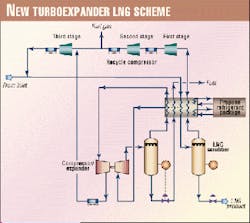
He explains that the refrigeration system provides refrigeration at relatively high temperature, while the turboexpander cycle does it at low levels (Fig. 2).
The cold vapors that are used as refrigeration media are recycled to the front end of the unit where they are compressed and returned to the process. This recycle helps to "lean" the inlet gas stream as well as acting as an internal "low level refrigerant stream." The ratio of recycle to the inlet is about 3:1.
After being conditioned, the gas stream enters the gas liquefaction stage. Here, the gas enters the main gas exchanger and is cooled to -40° F. The gas stream then splits: one stream moves to the turboexpander section; the other continues through the exchanger.
The side stream enters the turboexpander where it is expanded to 200 psig, decreasing the temperature to -171° F. The discharge of the expander is a two-phase stream that is sent to a separation stage or, depending on the composition and product specifications, to a special demethanizer column where the ethane and heavier components are separated.
The cold gas and liquid streams from the separation stage are directed to the gas exchanger, where they are warmed to ambient temperature and become part of the recycle stream. These streams are an important contributor to the energy balance of the unit, says Foglietta.
Depending on the amount of NGL in the gas, the liquid stream could leave the gas exchanger as a pressurized liquid or fuel gas.
The warm gas from the gas exchanger enters the booster compressor, where by virtue of the work extracted from the expansion process, the pressure is raised to 280 psig.
After being cooled to ambient temperature, this stream is then mixed with the main recycle stream.
The high-pressure gas stream that continued through the cooling process in the gas exchanger reaches a temperature of -170° F. before it is expanded to 15 psig. A temperature of -250° F. is achieved after this expansion with 67% of the mass flow liquefied, says Foglietta.
The remaining 33% off-gas vapor is sent back to the gas exchanger, where after providing refrigeration to the process it reaches 95° F. The main recycle stream is then compressed until it reaches the booster compressor discharge pressure, at which point it is combined with that stream before mixing and continuing to the final compression stage at the front end of the plant.
At a medium pressure level, a fuel gas stream is taken for turbines or engine drivers. Depending on the feed-pressure conditions, an inlet compression stage will be required, but this is a minor consumer, says Foglietta.
A further refinement of this scheme includes the use of staged expanders further to reduce the energy consumption. The flash stage would operate at 45 psig, to be then expanded to 15 psig.
The result is a much colder final stage. The vapors from the second flash are sent to the main exchanger.
The liquid produced is sent to a final subcooling stage before being delivered to the storage tank at almost atmospheric pressure. Vapors from the storage tank are captured and cross-exchanged with the liquid LNG before the expansion and sent to a boil-off compressor that will recover the vapors and send them to the recycle stream.
The refrigeration system consists of a two-stage propane cycle. The design includes the propane vaporization steps included in the main gas plate fin exchanger, using a thermo-syphon arrangement. The refrigeration temperature levels are set strategically to minimize the energy requirements.
In the case presented here, the refrigeration is set at -35° F. for low temperature, and 35° F. for high temperature.
To evaluate the process, ABB Randall utilized a simple energy index to measure the performance: horsepower per unit of mass liquefied. Table 1 shows a comparison of the process described with the other industry schemes.
Foglietta says that this process scheme requires that seven process streams be integrated into a single piece of equipment for maximum heat-transfer effectiveness.
With the refrigeration system providing only 22% of the duty required for the liquefaction, the exchanger construction is greatly simplified. The whole core is "cold box" packaged to minimize losses.
The fact that this process scheme uses standard industry equipment makes it more cost effective than the classical licensed unit, he says.
This technology also reduces cost to achieve an LNG facility to produce alternative fuel because all that is required is a connection point to a gas pipeline. Facility costs are further reduced by the fact that gas in the pipeline is already treated for transportation.
Australian plans
BHP Petroleum, Melbourne, and Linde AG, Wiesbaden, have put forward yet another vessel-based LNG design the companies say is feasible and economic for producing and exporting LNG from remote marginal gas fields.4
Called "cLNG," the liquefaction process is based on nitrogen cycle and has been used in LNG peak-shaving operations. The companies say, however, that it has a gas-conversion efficiency similar to conventional base-load LNG plants.
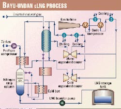
The process has been specifically targeted for GBS installation in the Bayu-Undan gas and condensate field, offshore Timor Sea Zone of Cooperation between Australia and Indonesia (Fig. 3).
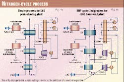
BHP and Linde state that the simple nitrogen cycle process (Fig. 4a) has been used successfully in several peak-shaving plants.
Treated gas is cooled by nitrogen refrigerant generated by a nitrogen expander cycle in which compressed nitrogen is pre-cooled in Exchanger E1. Then the majority of the flow is expanded by Turboexpander X2, which results in the required low-temperature nitrogen stream.
This cold nitrogen is then used to provide the bulk cooling of the natural gas in Exchangers E2 and E1. Optionally, a small stream of precooled nitrogen is further cooled in Exchanger E2 and then letdown in pressure through a valve to produce some very cold gas or liquid nitrogen.
This stream is used to provide the sub-cooling of the LNG in Exchanger E3. In some plants, say the companies, methane is added to the nitrogen refrigerant to improve the efficiency of the process.
The warmed nitrogen leaving exchanger E1 is compressed by Compressor C1 and is further compressed by the booster Compressor C2 driven by Turboexpander X2.
The nitrogen cycle process has several attractions for offshore LNG production, say the companies. The simple design, using a single regeneration cycle operating in single-phase gas, means that there are relatively few equipment items
The liquefaction section of the plant consists of a single compressor, a turboexpander, a cold box and three heat exchangers for the compressor coolers. This reduces the complexity and space requirements for the plant. No compressor suction or refrigerant surge drums are required nor their associated piping, valves, and instrumentation.
The companies note several inefficiencies in the nitrogen cycle process for larger base load plants as well as a few for the small peak shaving plants. But, they say, they have made several improvements to the process for cLNG: Fig. 4b shows the basic difference in configuration between the proven, simple nitrogen cycle process used in peak-shaving plants and the optimized nitrogen cycle used in cLNG process.
References
- Price, Brian C., and Mortko, Robert A., "Development of Mid-Scale and Floating LNG Facilities," GPA Annual Convention, Mar. 16-18, 1998, Dallas.
- Naklie, M., Harms, J., and San, Soo Cheong, "Evaluation supports floating LNG safety," World Oil, November 1999.
- Foglietta, Jorge H., "New LNG Process Scheme," GPA Annual Convention, Mar. 1-3, 1999, Nashville, Tenn.
- Dubar, Chris, Forcey, Timothy, Humphreys, "A Competitive Offshore LNG Scheme Utilising a Gravity Base Structure and Improved Nitrogen Cycle Process," LNG 12, May 4-7, 1998, Perth.
New vessel designs target delivery flexibility
IT IS CONCEIVABLE THAT THE economics of producing remote, marginal gas fields may depend nearly as much on flexibility of delivery as on flexibility of aggregation.
Heretofore, the expense of a LNG carrier as the key link between production and market has required not only large investment at the liquefaction point but also a nearly equally large investment in shore-based regasification.
That facility, to be economic, had to be connected via pipeline to a sufficiently large market behind it. Japan and Europe are obvious examples for which massive investments have been made in large, land-based receiving and regasification terminals.
But what if gas (as gas, not liquid) could be offloaded directly into a pipeline that then delivered it directly to market? In other words, what if the regasification process were also ship-based?
At least two such vessel designs promise that kind of flexibility. One employs LNG; the other compressed natural gas (CNG).
Shipboard regasification
Mobil Technology has again been busy at the idea of making the LNG chain more flexible, this time coming up with a design for shipboard regasification.
Glenn Campbell, Mobil Technology, Dallas, and Jay Zednik, Mobil Shipping & Transportation Co., Fairfax, Va., see among the advantages of such a system that it permits the delivery rate to emerging gas markets to be ramped up gradually, as demand grows.1
They also believe that the system can provide an uninterrupted supply of gas while a customer builds a conventional receiving terminal or can supplement a conventional terminal in high demand season.
The technology and associated equipment are simple and proven, they say. Pumps and vaporizers are installed on the LNG tanker to provide regasification of LNG aboard the vessel.
In the simple design, an LNG ship is moored to a piled single point mooring (SPM) equipped with a boom and rotating head to allow the ship to weathervane.
Flexible pipe transfers natural gas from the ship to a high-pressure swivel on the SPM. A conventional riser and subsea pipeline transports the gas to an onshore pipeline.
Process
In this design (Fig. 1), LNG stored in spherical tanks in the LNG carrier is withdrawn by the LNG unloading pump to a common LNG header.
In each tank are two LNG pumps, but one is sufficient to deliver a design rate of 600 cu m/hr of liquid.
LNG then passes to a recondenser to reabsorb the excess boil-off gas (BOG) from the tanks. How much BOG varies with the tanks' LNG inventory.
The BOG is recompressed to 7 bar (approximately 100 psi) before being sent to the recondenser for reabsorption in the LNG stream. That stream is then divided into two parallel LNG booster pumps that raise the pressure to 95 bar to meet the onshore distribution pressure requirement.
Downstream of the booster pumps, the LNG is metered before it flows through the vaporizers where it is heated to approximately 2° C. Seawater is used as the heating medium.
In order to reduce thermal cycling stress to the vaporizer, a minimum flow of a cryogenic fluid (LNG or BOG) through the vaporizer is required. Two vaporization trains are provided, one on either side of the ship's spherical storage tanks.
Seawater pumps lift seawater from two sea chests near the keel of the LNG carrier.
Two streams of superheated natural gas at about 2° C. at the outlet of the vaporizers combine before being sent to a subsea pipeline to shore via the SPM.
Among modifications to the LNG vessel to accommodate this process are new seawater inlets, outlets, and pumps; LNG booster pumps and additional LNG pipeing; intermediate-fluid LNG vaporizers; BOG compressors; and natural gas piping.
Campbell and Zednik believe the shipboard regasification system relies on proven technology and equipment to deliver uninterrupted supply of gas to emerging markets.
The natural gas delivery is, they say, quick with low capital outlays. And the technology is obviously transportable, thus reducing overall capital outlays.
Coiled pipe
Still another approach to flexibility of delivery doesn't use LNG at all.
Inventors of the "Coselle" pressure vessel and CNG carrier claim the technology improves the economics of shipping natural gas over short sea routes, unlocking many of stranded gas reserves.2
Central to this technology is a CNG containment system consisting of several miles of relatively small-diameter steel pipe coiled into a carousel-like container. (Coselle = coiled carousel container)Fig. 2 presents a rendering of the Coselle CNG carrier concept. - The Coselle CNG carrier consists of a series of coiled pipelines arranged in carousels in the vessel's hold (Fig. 2).
A joint industry project to examine the technology commenced in May 1999 with currently eight major companies (including BG) participating. The final meeting of its initial round of meetings occurred last month.
The joint industry project is focusing on monetizing smaller stranded gas reservoirs, transporting associated gas directly from a production platform, and shorter distance gas transport routes (up to 1,500 miles).
David Stenning of Cran & Stenning Technology Inc., Calgary, which developed the Coselle design, says that a large portion of a typical CNG carrier's capital cost comes from the gas-containment system and associated safety and gas control systems.
Coselles cost a fraction of conventional pressure bottles (or bullets), he says, and yet maintain at least an equivalent level of safety. For example, a scenario Stenning has run on a Coselle CNG carrier of 330 million cu ft capacity would cost about $110 million; an equivalent CNG "bottle" ship would cost at least $300 million.
Coselle technology
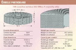
The central idea is to create a large but compact CNG storage system using pipe. Fig. 3 shows a typical Coselle configuration that consists of several miles of small diameter pipe coiled into a carousel.
According to Stenning, the Cosselle has inherent cost and safety advantages over conventional pressure vessels.The small diameter of the Coselle pipe decreases both the likelihood and consequences of rupture compared to large diameter vessels. Moreover, the design is less costly because 90% of the Coselle is made from conventional 6-in., 0.250-in. WT line-pipe that is mass manufactured by highly competitive industries.
Coselles, says Stenning, can easily be produced within the current pipe market for virtually any size of project. On the other hand, manufacture of large pressure vessels is a specialized industry with limited capacity to mass produce the thousands of vessels needed for a large marine CNG project.
Also, in a typical pressurized CNG vessel, manifolding hundreds of pressure bottles together, each with a control valve, two relief valves (as required by code), and drain is complex and expensive.
The Coselle design reduces the number of vessels with a corresponding reduction in the complexity of the manifolding and control systems.
Stenning says that a Coselle CNG carrier was designed around a double-hulled 60,000-dwt bulk carrier concept in order to develop the ship requirements and cost. In this design, Coselles are carried in stacks of six high within the ship's hold.
In total there are 18 stacks of Coselles (108 Coselles/ship). Each Coselle holds 3.09 million cu ft of sales gas, leading to a vessel capacity of 330 million cu ft.
Fig. 5 shows a general arrangement of the ship with its principal particulars. For safety, the holds are inerted with nitrogen in order to eliminate the danger of fire below deck. All valves and fittings are installed above deck to facilitate servicing.
Cranning says that the Coselle CNG technology has the potential to be the least cost gas-delivery system when the market is less than 2,500 miles from the reserves. It is significantly less costly than its alternatives, LNG and pipelines, when the transport distance is between 300 and 1,500 miles.
Since CNG can be loaded offshore, using conventional loading terminals, it can be used to transport associated gas directly from offshore platforms. This has the potential to alleviate the growing problem of associated gas disposal for offshore oil fields, especially in deep water.
References
- Campbell, Glenn, and Zednik, Jay, "Shipboard Regasification Terminal," GPA Annual Convention, Nashville, Tenn., Mar. 1-3, 1999.
- Stenning, David, "The Coselle CNG Carrier: A New Way to Ship Natural Gas by Sea," NOIA Conference, June 14-16, 1999, St. Johns, Newfoundland.
