Coiled tubing replaces sucker rods in beam pump test
A test in Argentina indicated that coiled tubing could replace sucker rods for reciprocating a subsurface pump and at the same time function as the production string on a shallow, marginal, or low-producing oil well.
This type of pumping system has the potential to save costs because of the smaller wellbores required and the likelihood of less failures than sucker rods and sucker-rod connections.
Coiled tubing
Coiled tubing has been used in the oil industry for a number of years, primarily for well service work, although some long-term downhole installations such as velocity strings are also in use.
In 1995, an idea was developed, based on hydraulic calculation, that for low volumes and shallow depths, pressure losses through small internal-diameter tubing would not prevent the tubing from serving as a production string. A subsurface pump was designed for this application, covered by a US patent.
This design allows for smaller, less-costly holes to be drilled. Larger hole sizes are often drilled only to allow the accommodation of sucker-rod and jointed tubing production systems
Another concern in pumping wells is the need for an annular space that collects fluids commingled from different zones and that acts as a chamber for segregating associated gas.
Slim holes for producing wells were discussed with YPF S.A. in early 1997, and it commissioned a pilot test.
At the beginning of the program, we knew that a slim hole cased with a small diameter such as 31/2 or even 27/8-in. string could be serviced with coiled tubing. Also, hollow sucker rods could pump and convey fluids to the surface.
But lack of available hollow sucker rods required another solution. This led to the idea of using coiled tubing, instead.
Tubing elongation caused by the tubing and fluid weight as well as pumping speed was a concern that was carefully considered. Simple calculations showed that elongation was not a problem at shallow depths, but a question remained regarding reciprocating speed. An actual test was the only way to know whether coiled tubing would sustain constant reciprocation, such as experienced by sucker rods.
Availability of an hydraulic pumping unit encouraged a test at slow speeds or strokes/min aimed at reducing the risk of failures. But a more aggressive approach was taken by testing the coiled-tubing production string with a standard beam pumping unit.
Design considerations
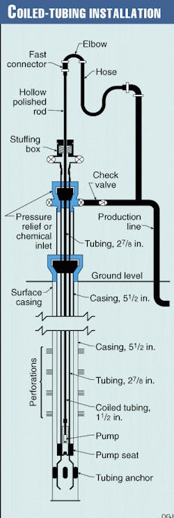
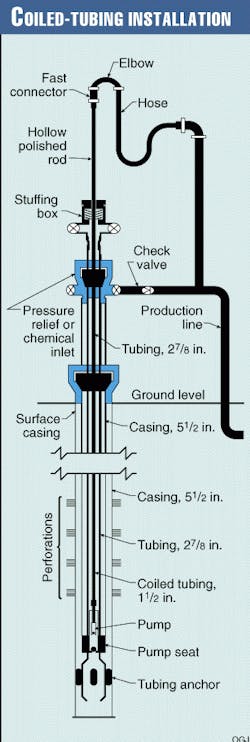
In early March 1998, a test plan was submitted for replacing sucker rods with coiled tubing inside 27/8-in. tubing (Fig. 1).
Before using coiled tubing for this application, one needs appropriate engineering software to predetermine working conditions and predict fatigue life. While running in the hole, straightening the tubing is required to prevent premature OD wear.
Other recommendations are that the coiled tubing should be new, and the coiled-tubing unit should have enough span between the injection head and the well head to allow visual observation of any bowing of the tubing.
Installation sequence
The following sequence was used for completing YPF's Well P-88 with coiled tubing:
- Obtained a suitable hollow-rod pump with a retrievable anchor attached to the bottom of the pump.
- Inserted a hollow-rod pump with a retrievable anchor into the well using a small winch. This could be done also with a crane or simply by hand.
- Installed a polished-rod clamp on the hollow rod, to hold the pump in its position on the well head.
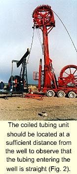
- Positioned a coil tubing unit aligned with the well (Fig. 2). - The coiled-tubing unit should be located at a sufficient distance from the well to observe that the tubing entering the well is straight (Fig. 2).
- Installed a coiled-tubing connector on the free end of the coiled tubing.
- Screwed the top end of the hollow rod to the coiled tubing connector.
- Ran in the hole the pump and coiled tubing to the pump setting depth.
- Secured the coiled tubing on the well head with a polished-rod clamp and slips.
- Cut coiled tubing.
- Installed a top-end coiled tubing connector.
- Positioned, aligned, and held a hollow polished rod with clamp and rod elevators.
- Screwed the bottom end of a hollow polished rod to the top end of the coiled tubing connector.
- Removed clamp and slips from the coiled tubing.
- Set pump anchor in desired position by maneuvering the hollow polished rod.
- Installed bridles and connected hollow polished rod to pump jack.
- Attached a high-pressure hose, with a quick hydraulic connector, to the top end of the hollow polished rod.
- Attached the free end of the hose, with a quick hydraulic connector, to the production manifold.
- Spaced out the pump.
- Adjusted all wellhead connections.
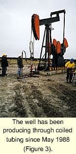
- Put well on production (Fig. 3). - The well has been producing through coiled tubing since May 1988 (Fig. 3).
This system was installed in late May 1998 and has since functioned without an incident. The well is monitored on a scheduled basis with surface surveillance equipment and dynamometers.
Software development
With the exception of some basic calculations on pressure losses, yield strength and elongation, the test in Argentina was conducted mostly on a "try and error" basis. But once the test proved to be successful, a software program was designed to determine coiled tubing fatigue, based on well data and pumping conditions.
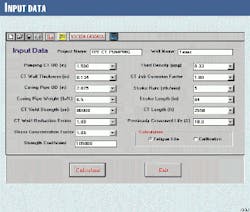
YPF contracted Maurer Engineering Inc. to develop CTPUMP. This software calculates fatigue life of the pumping system by considering input parameters such as casing and coiled tubing dimensions, fluid density, tubing material properties, tubing vertical length in the well, stroke length, and number of strokes/min.
This program also considers system fatigue life due to reciprocating coiled tubing and effects of buckling in compression. The following three steps were taken to evaluate fatigue life of the system:
- Calculate fatigue damage due to cycling on the gooseneck and over the spool (strain-controlled fatigue damage).
- Calculate fatigue damage due to cyclic reciprocation (stress-controlled fatigue damage).
- Sum these two components to calculate total fatigue damage.
Additionally, coiled-tubing wear was investigated. Preliminary studies based on nominal parameters indicated that coiled-tubing wear was not a problem for the desired 1-2 year life span.
Low-cycle fatigue
Based on extensive fatigue testing, Halliburton Energy Services and Quality Tubing Inc. developed an algorithm to predict coiled-tubing fatigue life as it is cycled on and off a reel and over a gooseneck.1 2 This algorithm was used to compute coiled-tubing low-cycle fatigue damage, which was included in Maurer Engineering's CTLIFE software.
Assuming that the total coiled-tubing low-cycle fatigue life is NL trips, after nL trips (nL < NL), the proportion of life consumed is determined by the relationship nL/NL.
Therefore, pumping life should be corrected by a factor of 1- (nL/NL).
Pumping motion
In a pumping application, coiled tubing subjected to repeated loads can develop cyclic stresses that lead to microscopic physical damage of the coiled-tubing material.
Even at stresses well below a given material's ultimate strength, this damage can accumulate with continued cycling until it develops into a crack or other damage that leads to coiled-tubing failure.
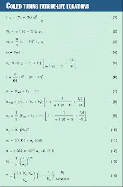
During reciprocating motion, the total force that the tubing receives includes inertial force (Fint), tubing weight (Fw), fluid weight (Ff), and stress due to buckling when the tubing is compressed (Fb). These forces are shown by Equation 1 (see equation box), where mt and mf are tubing weight and fluid weight inside the tubing, respectively (Equations 2 and 3), and w is the angular frequency during pumping (Equation 4).Forces due to tubing weight Ft and fluid weight Ff are equal to the right side of Equations 3 and 4, respectively.
When tubing is in compression, a bending stress is superimposed on the compressive stress. Equation 5 determines the total maximum compressive.3 In Equation 5, rc = (dc - d)/2 is the clearance between the inner coiled tubing (pump rod) and outer coiled tubing (casing), and I is the moment of inertial of the inner tubing (Equation 6).
The maximum tension stress can be derived with Equation 7. Therefore, the maximum stress amplitude is obtained by Equation 8 and the alternative stress by Equation 9.
Then a high-cycle fatigue empirical formula is used to predict fatigue damage for this case (Equation 10). In Equation 10, s'f and b are material constants known as the fatigue-strength coefficient and fatigue-strength exponent, respectively. The constant b is also commonly referred to as Basquin's exponent.These two material constants are determined by experiment. They are, however, generally model dependent.
There has not yet been any experimental work on high-cycle fatigue of coiled tubing. Based on published results for steel material,4 5 and with reference to data on coiled-tubing low-cycle fatigue obtained from Quality Tubing, our best estimate of the high-cycle fatigue strength coefficient and fatigue strength exponent is shown by Equations 11 and 12.
The fatigue-strength coefficient and fatigue-strength exponent can be adjusted in the model. Field data will become available as the coiled-tubing pumping system is used, after which the fatigue-strength coefficient and fatigue-strength exponent will be calibrated accordingly.
From Equation 9, one can obtain Equation 13.
Total damage
Equation 14 expresses total fatigue life (T) in years, using a safety factor of 0.7. In this equation, Kc is job-related corrosion factor, Kw is weld factor, and Ks is stress concentration factor due to other factors such as damage caused by improper use or accidental damage.
Corrosive environments in coiled-tubing operations, such as acid or H2S, will result in damage to the coiled tubing. The following corrosion factors are used to account for this damage and modify coiled-tubing fatigue life:6-8
- Kc = 1.0 for water and nitrogen.
- Kc = 0.66 for cement and acid.
- Kc = 0.50 for H2S.
Coiled-tubing fatigue life will be reduced at weld locations. The following weld factors are used to account for this reduction in life:9
- Kw = 1.0 for non-welded tubing section.
- Kw = 0.9 for bias-welded tubing section.
- Kw = 0.6 for tapered bias-welded tubing section.
- Kw = 0.45 for orbital (automatic) butt-welded tubing section.
- Kw = 0.35 for manual butt-welded tubing section.
- Kw = 0.2 for orbital (automatic) tapered butt-welded section.
- Kw = 0.15 for manual tapered butt-welded section.
The stress concentration factor Ks, due to other contributions, is always greater than 1. The default value of the stress concentration factor is 1.
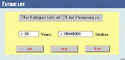
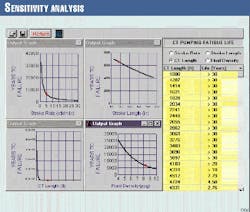
Figs. 4-6 illustrate an example run of the software. Fig. 4 is the input window and Fig. 6 is the sensitivity analyses that shows that fatigue life varies with stroke rate, stroke length, coiled-tubing length, and fluid density.
Future applications
While this pumping system (patent pending) has been developed for producing new slim or ultra slim, shallow, low producing wells, we believe the system can be applied to old wells cased with 51/2 or 7-in. tubulars.
Although we consider this innovation a major breakthrough in the industry, more tests are necessary to confirm its reliability.
Acknowledgment
The authors would like to express gratitude to YPF and Maurer Engineering for their permission to publish this article.
References
- Avakov, V.A., Foster, J.C., and Smith, E.J., "Coiled Tubing Life Prediction," Paper No. OTC7325, 25th Annual Offshore Technology Conference, Houston, May 1993.
- Yang, Y.S., Avakov, V.A., Smith, D.E., Martin, J.R., and Wu, J., "Coiled Tubing Fatigue Damage on Floating Vessels," Paper No. SPE46252, Third Annual SPE/ICoTA North American Coiled Tubing Roundtable, April 1998.
- Lubinski, A., Althouse, W.S., and Logan, J.L., "Helical Buckling of Tubing Sealed in Packers," JPT, pp. June 1962, pp.655-70.
- Dowing, N.E., Mechanical Behavior of Materials, Prentice Hall, 1993.
- Zahavi, E., Fatigue Design, CRC Press, 1996.
- Avakov, V.A., Coiled Tubing Fatigue Life Evaluation, Technical Report, Otis Engineering Corp., Dallas, August 1992.
- Comgan, M., and Gray, B., Determining the Working Life of a Coiled Tubing String, Technical Report, Petromin, March 1993.
- Scott, W.S., Coiled Tubing Fatigue Testing, TD94-22, Maurer Engineering, 1994.
- Quality Tubing, Inc., "Application Challenges Promote New Product Developments," Third Annual Conference on Emerging Technology-CT-Horizontal, Aberdeen, May 31-June 2, 1995.
The Authors
Humberto Leniek works with Coiled Tubing Americas, Houston. His work focuses on the design of hydraulic and mechanical pumping systems with coiled tubing. He previously worked with Amoco Argentina, Hughes Tool Co., and Baker-Hughes. Leniek is a graduate of an industrial college in Argentina.
Y.S. Yang is a petroleum engineer with Maurer Engineering Inc., Houston. He conducts numerical modeling and software development for coiled-tubing fatigue, collapse, burst, and diameter growth. Prior to joining Maurer, he was a research scientist at Rice University and worked with Precision Tube Technology in R&D.
Yang holds a PhD and an MS in space physics from Rice University and a BS in geophysics from Yunnan University, China.
