Geosteering techniques avoid production completions
A combination of innovative geosteering techniques, aided by state-of-the-art logging-while-drilling (LWD) technologies, allowed Mobil E&P Australia to remain within a narrow 2-m band while avoiding existing wellbores.
The 1997 project described in this article consists of the full-field development phase for the 75-million bbl Wandoo heavy oil field, located 50 km offshore Northwest Australia.
Geology
The low relief reservoir consists of two main unconsolidated units. The upper Unit A is a fine-grained greensand with permeability ranging from 50 to 3,000 md. This unit contains up to 50% glauconite with laterally continuous, hard siderite bands.
Reservoir quality improves with depth, becoming significantly better below the siderite beds. The siderite bands further subdivide Unit A into zones with the best reservoir, Subunit A3, located at its base.
The underlying Unit B, subdivided into two subunits, contains a fine to medium-grained quartz sand that grades downward to a glauconitic greensand. The best reservoir interval within the field is the upper Subunit B1-B2 with permeability in excess of 10 darcies.
The lower subunit, B3, has a glauconite content varying from 15 to 40%. The average thicknesses for these subunits A3, B1-B2, and B3 are 5, 3.5, and 8 m, respectively.
Development strategy
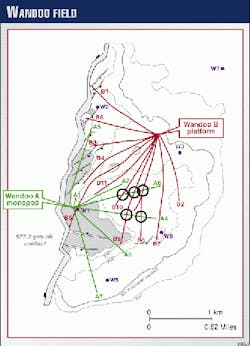
The development was performed in two stages, 1 year apart, consisting of the Wandoo A and B. Located near the crest of the structure in the best part of the field, the first horizontal development wells were drilled from the five-slot monopod platform, Wandoo A.
Reservoir simulation indicated field development off the Wandoo B platform would require a higher drainage density in the main part of the reservoir, especially around wells accessed from the Wandoo A monopod.
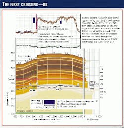
Additionally, studies showed infill wells from Wandoo B were far more economic than redrills off the Wandoo A monopod. However, access to these infill locations from the Wandoo B platform required well crossings of existing producing completions (Fig. 1).
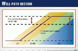
Coning studies indicated that a wellbore in Unit B1-B2, if placed outside a narrow 2-m window, 4.5 m below the gas-oil contact and 16 m above the oil-water contact, would result in premature gas and water coning and reduced recovery.
A wellbore in Unit A3 of the lower permeability unit contains a larger 5.5-m vertical window-also starting 4.5 m below the gas-oil contact-before coning becomes critical. Both the Wandoo A and Wandoo B wells were placed within these coning boundaries.
In addition to placing the wellbore within these fluid-contact-defined boundaries, to become productive, a wellbore in the 5-m thick A3 reservoir must also be positioned in a 0.6-m sweet spot located at the peak of a resistivity ramp.
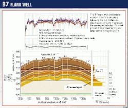
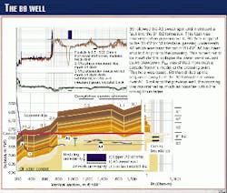
Because the Wandoo B platform is located northeast of the field crest, every B well must be approached from the flank, initially following the lower coning boundary. From this lower boundary, the well intersects and follows the A3 sweet spot up the dip closure to the top of the 5.5-m window, horizontally breaking into the B1-B2 unit (Fig. 2).
Well-crossing technique
Two wells crossing within a 2 m thick coning window is not possible using the two-sigma survey error, geometric-collision avoidance technique, which required 5.2 to 7.7 m of vertical separation
Therefore, the team developed an alternative method for collision avoidance, with the clastic sequence-a marine deposit with laterally comformable characteristics-aiding in this objective. Wireline log correlations from vertical appraisal wells indicated a layered stratigraphic sequence 1-2 m thick, with laterally consistent resistivity and gamma ray measurements.
Thus, the well team determined they could avoid the producing horizon of the crossed well by drilling into the adjacent subunit, using the vertical separation as defined by the combined effects of the bed thickness of these subunits, and the vertical resolution of the near-horizontal logging-while-drilling (LWD) sensors.
In practice, however, there are factors that can degrade the accuracy in the well crossing clearance using this technique:
- The distance between the LWD measurement and the build or drop tendency of the bottomhole assembly (BHA) producing a depth lag effect.
- Lateral variations in stratigraphic thickness and log signature.
- Sparse real-time data from the low-telemetry bandwidth typically available with real-time measurements.
- Difficulty in distinguishing one subunit from another.
- Errors in modeling the vertical resolution of the near-horizontal LWD sensors from wireline logs recorded perpendicular to the formation.
Stratigraphic signature
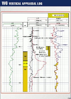
Unit A3 has a laterally consistent log signature consisting of a 2-3 m resistivity ramp with measurements of 1.5 to 3.5 ohm-m at 55 gAPI (gamma ray units). This unit is located above a 2-3 m thick, 3 ohm-m, 40 gAPI layer (Fig. 3). The most productive interval in the A3 reservoir is a 0.6-m subunit located at the bottom of this ramp.
Unit B1-B2 has a high resistivity of 100 to 800 ohm-m at 30 to 40 gAPI; while unit B3 has a resistivity of between 20 and 80 ohm-m with a gamma ray varying from 35 to 50 gAPI.
Tool response
To geosteer within unit A3, it became necessary to distinguish subunit characteristics such as the top and base of A3 and the sweet spot. This required resistivity sensors accurate to 0.2 ohm-m over a range of 1 to 5 ohm-m, a bed resolution of 0.6 m, and gamma ray sensor accuracy to 5 gAPI.
Unit B required a resistivity range to at least 300 ohm-m. An immediate response to a change in gamma ray or resistivity reading became necessary to geosteer the wellbore within a subunit for well crossings and to geosteer through the 0.6-m thick A3 sweet spot.
The departure-to-vertical depth ratio of the horizontal wells ranged from 2.5 to 3.5. To ensure the extended-reach wells reached TD, the operator had to control dogleg severity to minimize torque and drag.
From the experience of the Wandoo A wells, the control of the wellbore trajectory in Unit A was affected by the presence of siderite nodule layers, particularly at angles greater than 88
Any uncontrolled drop in true vertical depth (TVD) associated with siderite at this point could result in premature water production. Thus, a continuous near-bit inclinometer sensor was required to circumvent or minimize these siderite-induced inclination changes, and to enable accurate geometric drilling within the cone boundaries, particularly at the well heel.
Additionally, any unexpected changes in inclination during well crossings had to be recognized as soon as possible. The near-bit inclinometer was also considered useful for low-side sidetracks, which provided contingency readings in case the drain hole encountered significant sections of nonreservoir or even entered B1-B2 outside the allowed 2-m gas-and-water coning window.
To satisfy these immediate response requirements, the three sensors-resistivity, gamma ray, and inclination-had to be kept as close to the bit as possible. The tool selected for the project was Schlumberger's GeoSteering Tool, an instrumented motor embedded with near-bit inclination, gamma ray, and laterolog measurement sensors. This assembly uses the bit as an electrode (Rbit).
Modeling results showed the vertical bed resolution of this at-bit resistivity measurement, when positioned parallel to the bed boundaries, became shallow enough to identify the 0.6-m subunits with bed resolution constant over the 1 to 300 ohm-m resistivity range. The drilling operation used water-based drilling mud with sized salt.
A 2-Mhz compensated dual resistivity tool (CDR) was also included in the BHA to provide measurements consistent with existing horizontal wells and to provide a measurement in the 121/4-in. section of the Wandoo B platform wells.
The separation between the phase and the attenuation resistivities from the CDR, as caused by polarization at resistivity contrasts and dissimilar investigation depths, proved extremely useful for interpretation and near real-time correlation.
These separations provided repeatable and recognizable log signatures at each siderite layer and at the peak of the A3 ramp.
Prejob modeling
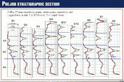
The rimary objective of prejob modeling was to create a stratigraphic sequence of expected log responses for the gamma ray, geosteering tool, and CDR resistivity measurements. Reference to these expected log responses while geosteering will indicate the position of the bit in the sequence.
Because identical resistivity and gamma ray values occur at more than one depth, there is an ambiguity that can only be resolved by knowing the starting point in the sequence. Thus, the second objective for prejob modeling was to establish the 95/8-in. casing shoe in the stratigraphic sequence.
The prejob modeling was made with wireline laterologs from the appraisal wells and CDR logs from the first nine Wandoo B wells (Fig. 4), which were geometrically batch-drilled to the casing landing point.
Circulating density
Engineers conducted a series of leakoff tests in the offset wells to determine the equivalent circulating density and separation required to drill the crossings without fracturing the rock between the new and existing wells. This distance was estimated to be 1 m, which defined the closest allowable separation.
The existing wells were shut in prior to the crossings, minimizing the differential pressure between the new and existing wells. The wellhead pressures for the crossed wells were monitored while drilling, watching closely for an increase that would indicate mud entry.
Crossings
The existing horizontal wellbore logs were examined in the vicinity of the proposed well crossings for the optimum crossing location. As the B wells were planned to cross over the A wells, this optimum location comprised low points in the A wells within the 2-m TVD gas and water coning boundaries.
Ideally, the crossing point contained a subunit interface within the coning boundaries located away from any faults visible on the seismic survey.
For the project, the well team planned to:
- Cross over well A6 with B10.
- Cross over A6 and A4 with B8.
- Cross under A6 and over A4 with B9.
Comparing the Wandoo A 2-Mhz logs to the resistivity model, the team identified the subunit in the sequence containing the A wells, positioned at the crossing point. To ensure a vertical separation of 1 m, the over-crossings were drilled near the top of the overlying subunit.
Geosteering in the upper half of unit A3 was made possible by following the midpoint of the resistivity ramp, ensuring a lower A3 thickness between wells in Unit B1-B2. The B1-B2 over B3 crossings, however, became more difficult due to the less-consistent internal structure of B1-B2, and the poor correlation and lateral variability of B3.
One way to achieve such a crossing is to tag the B1-B2 to B3 interface at a safe distance prior to the crossing, ensuring a fix on the TVD interface. The crossing was then made from a safe vertical distance above.
This tag point, however, must be close to the crossing point to avoid an unknown dip that could significantly reduce the clearance. The tag and well crossing must also be achieved within the constraints of the coning boundaries.
If the reservoir development plan permits, another approach can be made to relax the 2-m constraint by using a 95/8-in. casing string to isolate the wellbore. In the one instance, A6 underpassed B9 by 4.6 m using this method. This under-crossing was interesting in that the lower well showed a water cone from the recently shut-in well above.
The most difficult well crossing, which relied on recognition of the B1-B2 subunits, required a pilot hole to be drilled off the previous horizontal well. In this case, B8 was sidetracked between A6 and A4 to further appraise the B9 over A4 cross-point.
This horizontal pilot hole confirmed the subunits were recognizable and facilitated an interpretation of the position of the existing A4 well within these subunits.
Learning experience
The geosteering tool's bit resistivity and gamma ray readings remained consistent within the criteria of 0.2 ohm-m and 5 gAPI.
Additionally, The Rbit resistivity provided sufficient bed resolution to identify the subunits. At this depth a reduction in weight on bit was usually enough for the formation to turn the drilling assembly into the sweet spot.
Above and below the sweet spot, the Rbit and near-bit gamma ray readings were slightly lower, respectively. This indicated a drift out the top or the bottom of the sweet spot. When bit weight variations were not able to prevent this drift, it was usually possible to follow the geological undulations with short slides (Fig. 5).
The gamma ray drop at the base of the A3 ramp was much sharper than the wireline gamma ray measurements. Thus, it became easier to pick this marker than the resistivity drop at the ramp base.
The geosteering tool provides an azimuthally focussed resistivity reading that indicated the siderites while sliding. Additionally, the bit resistivity measurement resolved each subunit within the higher resistivity B1-B2 unit, which was not possible with a multispaced 2-Mhz tool.
The subseismic faults identified while drilling tended to flatten the dips between the faults in an already low relief structure. What was interpreted as a low dip on the seismic survey became a combination of a very low dip and several small faults.
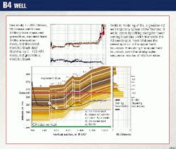
With wellsite modeling, however, it was possible to produce geological cross-sections sufficiently accurate to design a sidetrack if necessary. This additional geological variable did not impact the well-crossing strategy (Fig. 6).
There are several degrees of freedom available to a log analyst when creating a geological section based on matching log responses. For example model layer thickness, resistivities, and apparent dips are all variable.
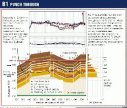
Thus, it is possible to gain a false sense of confidence in a model based on a single well match. The same layer thickness and resistivities, however, provided a consistent match with all the wells. Additionally, the B1 well contained 600 m of section that included a sidetrack. The model matched both wells, confirming the layer thickness and resistivities are representative of the Wandoo field (Fig. 7).
The inclination measurement at the bit limited the inadvertent deviations from the planned well trajectories to a depth amplitude of 0.5 m while drilling geometric targets such as along the upper coning boundary, or geological targets such as the A3 sweet spot at the base of the resistivity ramp.
These undulations were 2 m thick in the Wandoo A wells and drilled without a near-bit inclinometer. Unintentional directional changes did occur on intersection with siderite streaks, particularly at angles greater than 88
Computing well separation
There are two independent methods of computing the actual well separations at the crossing points between the A and B wells after drilling; a geometric calculation and log modeling. The geometric calculation uses the surveys from each well in a closest approach calculation.
The log modeling approach computes a relative separation based on matching both log responses with the stratigraphic sequence. This is a two-step process. With the B well surveys fixed, slices of true vertical thickness log model are dipped and moved vertically to build a cross section, whose forward model matches the measured B logs.
Then, with the cross section fixed, the two crossed A wells are moved vertically to make the forward model match the measured A logs. The surveys from the A wells still define the departure, but the TVD is disregarded. The vertical separation between the A and B wells calculated with this method agreed reasonably well with the geometric closest approach (Figs. 8 and 9).
The geometric location of B9 was also verified using vertical depths derived from a pressure measurement recorded from a production log while the well was shut in. The vertical depth difference was 0.5 to 1.5 m.
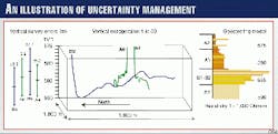
The final position of each crossed well is represented on the geological cross section by an uncertainty rectangle. The vertical axis of this rectangle is the modeling uncertainty, whose vertical dimension is defined by the amount the crossed well can be moved in the stratigraphic sequence before the log match becomes unambiguously poor. The horizontal dimension of this rectangle is calculated from the crossed well industry-standard 2-sigma azimuth uncertainty.
Uncertainty rectangles were also used to represent the wells to be crossed on the log depth display. The horizontal axis of this rectangle represents the range of log values read on the well to be crossed up and down from the geometrically defined crossing point.
The measured depth interval used to define this log value range depends on the azimuthal uncertainty of the B well. A large B-well azimuthal uncertainty makes a long A-well measured depth interval which will contain the crossing point. The vertical axis of this uncertainty rectangle represents the range of B well measured depths which will contain the crossing. This depends on the azimuthal uncertainty of the A well.
To avoid a collision, the B well log should not coincide with the A well log resistivity-depth and gamma ray-depth uncertainty rectangles.
Any technique to avoid drilling into existing completions is an exercise in managing uncertainty. In this case the geometric azimuthal uncertainty of the interwoven A and B horizontal wells was acceptable, but the vertical uncertainty was not. The vertical uncertainty was reduced to an acceptable distance using geosteering (Fig. 10).
Acknowledgments
The authors wish to thank the Wandoo joint venture partners, Mobil Exploration & Producing Australia Pty Ltd. and Wandoo Petroleum Pty Ltd. for permission to publish this article.
Bibliography
- Fabian, M.R., "Wandoo: The Development of a Marginal Field," APPEA Journal, vol. 39, Part 1, 1999, p. 523-31.
- Carnegie, A., Roberts, N., and Cline, I., "Application of New Generation Technology to Horizontal Well Production Logging-Examples from the North West Shelf of Australia," SPE paper 50718, presented at the Asia Pacific Oil & Gas Conference, Oct. 14, 1998.
- "Modeling Logs for Horizontal Well Planning and Evaluation," Oilfield Review 7, winter 1995.
The Authors
John Edwards has worked for Schlumberger since 1978. He initially began working in wireline, log analysis, marketing, and field management positions, but more recently has worked with Anadrill as a geosteering specialist. These assignments have been in numerous countries in the Far and Middle East. Edwards is currently marketing manager of the Sugarland Product Center and has published several SPE papers on a variety of subjects including structural interpretation from VSP, tandem density device for logging ovalized boreholes, and geosteering.
Peter Hillock graduated from the University of Adelaide in 1985 with a BS in geology. He worked as a wireline logging engineer in the mining industry for the next 2 years. In 1998, Hillock returned to the University of Adelaide and completed an honours degree in petroleum geology and geophysics. He has 10 years' experience in Australia and South East Asia as a geologist and petrophysicist with Western Mining Corp., Ampolex Ltd., and Mobil Exploration & Producing Australia Pty Ltd.
Mark Pogson is the engineering director for JWE Australia, an operations and petroleum engineering consultancy with business throughout Australia and Southeast Asia. He has held numerous staff positions as a petroleum engineer with operating companies in both the UK and Australia. Pogson began his career in research, covering a variety of subjects from solid state physics, chemical cngineering, and reservoir engineering. He obtained a BS and PhD in chemistry from the University of Leicester and an MS in petroleum engineering from Imperial College, London.
Gordon Nicholl is a consulting drilling specialist in New Zealand with broad experience in all aspects of drilling and completions operations. He has 21 years' industry experience with major and independent operators in North and South America, Southesast Asia, Australia, and New Zealand. Nicholl holds a BS in mechanical engineering from the University of Calgary (1979).
This article was adapted from SPE paper 56452 presented at the SPE Annual Meeting in Houston, Oct. 3-6, 1999.
