New membrane process debottlenecks solvent dewaxing unit
Availability of extra cold solvent in an existing solvent dewaxing unit (SDU) can increase dewaxed oil production by debottlenecking refrigeration, solvent recovery, and filtration sections of the unit.1
Mobil did just this by adding an innovative membrane process, called Max-Dewax, to its Beaumont, Tex., refinery.
The process selectively recovers cold solvent from the filtrate in an SDU. With this application, the firm developed the first large-scale commercial application of organic membranes for liquid-liquid hydrocarbon separation in the refining or petrochemical area.2
Adding this process to an existing unit costs less than one-third the capital cost of conventional unit expansion. Therefore, a refiner can use Max-Dewax inexpensively to increase lube and wax production.
The process can also significantly reduce the cost of lube or wax production per barrel of oil. For a blocked-mode dewaxer/deoiler unit, it increases stream time for additional wax production.
Mobil and W. R. Grace jointly developed this new technology. In 1994-1996, the two companies successfully demonstrated the technology in commercial-scale equipment with refinery feeds. The commercial unit, streamed in May 1998, at Mobil's Beaumont refinery, has run safely, reliably, and smoothly with excellent performance.
SDU limitations
An SDU removes the waxy components from the lube raffinate to achieve desired low temperature, rheological properties for finished base oil. Properties set by the dewaxing process include pour point, cloud point, and low-temperature fluidity.
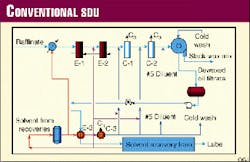
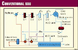
Fig. 1 shows the major components of an SDU. The unit first mixes lube raffinate from an aromatic extraction unit or a hydrocracker with primary solvent. Heat exchange with a cold lube oil/solvent filtrate stream followed by exchange with a refrigerant stream in chillers (C-1, C-2), initially cools the mixture.
The addition of cold solvent further downstream to the lube-solvent mixture ensures good wax separation and filtration characteristics. Heat exchange with other cold process streams or by refrigeration produces this additional cold solvent, also called secondary dilution, tertiary dilution, etc.
When the desired feed temperature is reached, rotary drums filter the lube-solvent mixture to separate slack wax from the lube-solvent filtrate. The filtrate, typically 80-90% solvent, then chills other process streams. Next, it proceeds to a solvent recovery section to separate the solvent and the dewaxed oil.
The SDU comprises three major sections: refrigeration, filtration, and solvent recovery. Typically, one or more of these sections limits the dewaxed oil production capacity.
Refrigeration-system design or operating constraints can limit the ability to achieve the desired filter-feed temperature. There may be insufficient cold solvent, particularly tertiary solvent, to maintain the optimal liquid-solids ratio in the filter feed and to achieve the target feed-mix viscosity. Both refrigeration design and operating constraints affect the number of filters required to support a given production rate.
Finally, the solvent-recovery section may have flash towers that are hydraulically limited or may be constrained by the heat input possible through the steam heaters or fired furnace.
Membrane process
In the Max-Dewax process, a proprietary polyimide membrane removes methyl-ethyl ketone (MEK) and toluene solvents from the dewaxed oil filtrate stream leaving the filtrate receiver.
The process recovers the solvent at or near dewaxing temperatures, which allows the recovered solvent to recycle to the dewaxing process without the need for additional cooling. This additional solvent decreases the filter feed viscosity, which thereby increases the filtration rates.
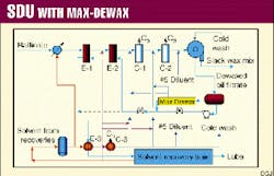
Fig. 2 shows how a Max-Dewax unit is placed within an SDU.
The process can selectively recover up to 50% of the cold solvent in the dewaxed oil filtrate. This solvent can be directly used for supplementing secondary and tertiary dilutions. After installation of the process, the SDU no longer needs the cold filtrate recycle and the bypass of the solvent filtrate exchangers, shown as a dotted arrow in Fig. 2.
The closed bypass now forces all filtrate across exchangers E-1 or E-2, which increases overall energy efficiency of the process. The use of essentially pure cold solvent from the membrane unit instead of cold filtrate increases filtration rate, lowers slack wax oil content, and increases lube oil yield.
Even with no bypass, the membrane recovers 25% of the cold solvent, which debottlenecks the refrigeration unit by about 10%. The cold solvent decreases the solvent refrigeration needs more than any increase in refrigeration required as a result of a higher feed temperature from E-2.
Membrane separation operates in a manner similar to other pressure-driven processes. The cold lube-oil filtrate, typically at 218 to 0° C., enters the membrane unit at a pressure of between 30-45 barg.
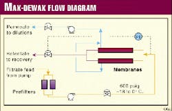
Fig. 3 shows the dewaxed oil-solvent mixture leaving the filtrate receiver. The mixture first goes to a bank of conventional cartridge-style filters to remove scale and any wax crystals present in the feed stream.
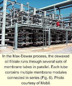
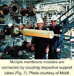
Pumps then send the feed to a set of membrane housings, all operating in parallel, which contain spiral-wound membrane modules. Each membrane housing contains multiple membrane modules connected in series by coupling their respective support tubes.
The membrane unit separates the dewaxed oil filtrate into an essentially pure cold solvent stream, referred to as the "permeate," and a retentate stream composed of the dewaxed oil and the unrecovered portion of solvent.
The permeate exits the membrane at essentially atmospheric pressure. Pumps then send it directly to the dewaxing chilling train as dilution solvent. The retentate exits the membrane unit and is let down to the conventional solvent recovery section after heat exchange with the dewaxer feed in double pipe exchangers.
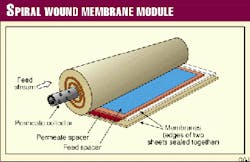
Fig. 4 shows a schematic of a spiral-wound module. Within the module, the feed flows under pressure through a carefully designed feed channel where some of the solvent selectively permeates the membrane while the oil and the remaining solvent are held back.
The solvent passes through the semipermeable membrane at a rate controlled by the difference between feed pressure and the osmotic pressure of the system. Lube oil will also transport across the membrane under diffusion control at a relatively slow rate dictated by the inherent membrane selectivity.
The clean permeate that is essentially at atmospheric pressure flows radially through the membrane envelope. The central support tube of the module collects this permeate.
External to the module, the permeate flows to a permeate-surge vessel from which it is pumped back to the dewaxing unit for reuse as a cold dilution solvent. The membrane and its associated backing material (a combined thickness of 100-350 microns) entirely support the large radial pressure drop.
Technology development
A multidisciplinary team from Mobil's Beaumont refinery, Mobil's technical center, Paulsboro, NJ, and Grace's Columbia, Md., research center and Littleton, Colo., production facility conducted the commercialization effort.
Some of the key challenges that Grace and Mobil successfully addressed were:
- Development of a commercially robust membrane film. The film has both 99%+ separation selectivity and an economically viable solvent flux at process temperatures. Scale up of the membrane manufacturing process to commercial film casting equipment represented a factor of 1,000 increase in scale from the laboratory preparations.
- Design and construction of a high specific surface area spiral wound module. The module resists the extremely aggressive solvent environment and is sufficiently robust for refinery applications.
Design activities included the design of feed and permeate channel spacers, formulation of solvent resistant adhesives, and optimization of membrane drying and module construction procedures. Non-destructive quality control tests for evaluating membrane module integrity were also developed as part of this objective.
- Provision for a constant solvent separation rate and consistent permeate purity. The new process provides for both a constant solvent separation rate and consistent permeate purity while accommodating a wide range of feedstocks and particulate-contaminant levels inherent in the dewaxing process.
As shown by the demonstration and commercial units, Max-Dewax is a proven process and offers the following advantages to the refiner:
Demonstration unit description
The demonstration unit came on stream in November 1994. Mobil and W.R. Grace conducted a variety of process variable studies through April 1995. The companies initiated a steady-state demonstration run in May 1995; the unit was shut down in August 1996 after successfully meeting all program objectives.
The demonstration unit had a 600 cu m/day (3,700 b/d) feed capacity. It sat adjacent the ketone 2 SDU at Mobil's Beaumont refinery.
The SDU uses a mixture of MEK and toluene to produce a range of lube-oil base stocks. The design size of the membrane demonstration unit allowed it to process about one-tenth of the total dewaxed oil filtrate stream.
The demonstration unit was similar to Fig. 3, except it had six tubes of membrane modules.
The existing ketone 2 filtrate pump (not shown) fed the lube-oil filtrate, which is a mixture of dewaxed oil and dewaxing solvents, to a set of prefilters to remove entrained particulates. Solvent-wash facilities allowed the prefilters to remove accumulated deposits as needed.
The demonstration unit used commercial-sized modules to minimize the risk of subsequent scale-up.
Demonstration run
Results of the 16-month steady-state demonstration run are shown in Fig. 5.
Fig. 5a shows permeate production rates for several base oil stocks for a set of six tubes, each containing six modules in series. Inlet pressure was 41 barg, and permeate pressure was 0.3 barg.
Initial permeate production was in the range of 6-8 cu m/hr, depending on the feedstock. As expected, the permeate rate for lighter lube stocks was higher than for the heavier stocks; lighter stocks have a lower feed viscosity and a correspondingly smaller mass transport boundary layer thickness.
The permeate rate decreased slowly with time for each stock. This is the result of irreversible compaction of the structure just below the dense working layer of the membrane. Increasing feed pressure can compensate for this decrease in permeate rate.
Fig. 5b shows the corresponding permeate oil content during the steady state run. The oil content of the permeate was generally less than 1 wt % except during initial start-up.
As previously discussed, the oil content decreased with time as a result of compaction. The permeate oil content decreased slightly as the lube base oil viscosity increased.
During the demonstration run, Mobil and W. R. Grace conducted a thorough process variable study to identify membrane unit performance at normal and upset conditions. The companies also evaluated start-up and shut-down procedures and collected sufficient data to build a process model to evaluate design trade-offs, operating strategy, and membrane life.
Tests conducted at the end of the program demonstrated the mechanical integrity of the membrane module. Intentional repeated start-up/shut-down cycles subjected the modules to significant thermal and hydrodynamic shock.
Post-operational analysis of the modules used in the steady state demonstration run showed some telescoping of the membranes, but revealed no other damage to any of the module components. The design of the current generation of modules provides additional protection against telescoping.
Commercial unit performance
Successful completion of the demonstration project led to the first commercial installation in May 1998 at the Beaumont refinery.
This unit, designed for an ultimate feed rate of 11,500 cu m/day (72,000 b/d), is the largest membrane separator of liquid phase organics in the world. Fig. 6 shows the banks of membrane housings that contain the spiral-wound membrane modules. Fig. 7 shows a loaded membrane cartridge. The throughput is currently 5,800 cu m/day (36,000 b/d), consistent with existing permeate demand.
Expansion of the membrane unit is possible by adding additional membrane surface area stage-wise as permeate demand increases. Plant commissioning and start-up were uneventful; the plant produced on-specification permeate within 1 hr of being on stream. Performance of the commercial unit has been well within parameters defined by the demonstration project.
Fig. 8 illustrates plant performance during the first 14 months of operation. As expected, the initial permeate production rate of about 70 cu m/hr decreased slowly to about 40 cu m/hr as a result of membrane compaction.
The temporary decrease in permeate rates (Fig. 8a) during and immediately after the heavy neutral lube oil blocks is the expected consequence of changes in solvent composition required to run this stock on the dewaxing unit. This impact is reversed once the solvent composition is readjusted for the light/medium neutral product slate typical for this dewaxing unit.
The process recycles the permeate to the dewaxer-feed chilling train and injects the permeate at various locations under both flow and temperature control. The essentially steady rate of the permeate-production level facilitates control of these multiple solvent recycle streams.
Permeate production in the commercial plant closely tracks that of the demonstration unit. The slightly superior performance of the commercial plant is the result of continuing improvement in membrane-module design.
Fig. 8b shows that the permeate purity has been excellent since initial start-up. Oil content of the permeate ranges from 0.2 to 0.8 wt %, depending on the base oil stock being run. The consistent quality of the permeate allows it to be used as solvent dilution throughout the dewaxer feed chilling train.
Economics
As indicated previously, membranes can improve solvent dewaxing process economics in several ways.
Increased lube base oil or increased wax production is the strongest economic driver and generally results in the shortest capital payout period. If, however, base oil demand is fixed, installation of the membranes will affect substantial decreases in energy consumption and greenhouse gas emissions while simultaneously reducing feedstock costs.
In either case, the capital cost of the membrane unit ($5.5 million) is substantially less than that of a conventional upgrade alone.
For example, the objective of the Max-Dewax unit at Mobil's Beaumont refinery was to maximize base oil production up to the capacity of the existing refrigeration compressors. A comprehensive engineering study had indicated that expansion beyond that point would be cost prohibitive.
Prior to installation of the membranes, refrigeration and solvent-handling capacity in the dewaxed oil recovery section limited the SDU when the unit was running light neutral stock. When running heavier stocks, both chilling train hydraulic capacity and filter surface area availability limited the dewaxing unit.
The process, combined with selected ancillary equipment upgrades, increased average base oil production by over 25 vol % and improved dewaxed oil yields by 3-5%. To estimate the economic benefit of the new process, the net improvement in the SDU was apportioned between improvement attributed to Max-Dewax and to other ancillary equipment.
Table 1 summarizes the economics of installation at Beaumont. The total energy consumption in the post expansion case was essentially the same as before the expansion. Consequently, the membrane process reduced energy use per unit volume of product by nearly 20%.
The installed cost of the membrane unit was about one-third of that which would have been required for equivalent process improvements using conventional technology. The increase in plant net profitability paid back the capital expenditure in less than 1 year . These benefits do not take into account credit for lowering oil content of slackwax in this analysis.
Mobil has further simplified the design of the unit by building modular units. Typically, a Max-Dewax unit to debottleneck a 800 cu m/day (5,000 b/d) lube dewaxing unit by 10-20% can be assembled off-site and shipped by road in four skid-mounted sections. This minimizes unit footprint and on-site construction and allows for quick installation and commissioning.
References
- Gould, R.M., McNally, D., Minhas, B.S., Smiley, P.H., Swango, W.A., White, L.S., and Wildemuth, C.R., 1998 AIChE Spring National Meeting, New Orleans, March 1998.
- Hagg, M.B., "Membranes in Process Industry: A Review of Applications and Novel Developments," Separation and Purification Methods, Vol. 27, No.1, 1998, p. 51.
The Authors
Nazeer A. Bhore is a licensing manager at Mobil Technology Co., Paulsboro, NJ. He has more than 10 years' experience at Mobil in various refining functions such as research, engineering, technical services, and technology marketing. He holds a PhD in chemical engineering from the University of Delaware, Newark, and is a graduate of the Wharton Management Program, Philadelphia.
Ron M. Gould is a senior member of the process research and engineering staff at Mobil Technology Co. He is currently responsible for process design, development, and technical support of Mobil's lubricant manufacturing operations. Gould holds a BChE degree from the University of Delaware, Newark, and an MS and PhD in chemical engineering from the University of Illinois, Urbana-Champaign, Ill.
Solomon M. Jacob is a licensing executive with Mobil Technology Co. He has more than 31 years of experience in petroleum industry and has held various management positions within Mobil. Jacob holds a PhD in chemical engineering from Northwestern University, Evanston, Ill.
Peter O. Staffeld is a licensing manager for Mobil Technology Co. He started with Mobil in 1988, and has worked in the catalytic reforming, resid upgrading, and planning areas. Staffeld holds a BS in chemical engineering from Michigan State, East Lansing, and a PhD from the University of Pennsylvania, Philadelphia.
Dennis McNally is the dewaxing process engineer at the Mobil Beaumont refinery. In the last 26 years with the refinery, McNally has been filterman, outside assistant operator, operator 'A' on both ketone units, relief shift foreman, and control supervisor on the dewaxing console
Pat H. Smiley is a maintenance engineer at the Mobil Beaumont refinery. In 9 years with Mobil, he has been in project engineering for instrument and electrical projects and maintenance engineering in the lube dewaxing units. Smiley holds a BS in electrical engineering from Georgia Tech, Atlanta.
Craig R. Wildemuth is the general manager of Grace Davison Membranes, Littleton, Colo. He has been with Grace for 9 years. Wildemuth holds an MS in chemical engineering from University of California at Berkeley.
