Use of dry gas, nitrogen improves FCCU reactor pressure control
Having found that the traditional method of controlling reactor pressure during fluid catalytic cracking unit (FCCU) start-ups had certain disadvantages, Sinopec's Shijiazhuang refinery, located in the Hebei Province, developed a new method.
The company uses high-pressure dry gas or nitrogen, instead of the traditional steam, to gain more flexibility and stability. The process also saves time and money.
Reactor-pressure control is one of the most crucial process parameters during the initial stage of an FCCU start-up. The quality of this control directly influences the catalyst fluidization between the reactor and the regenerator and the catalyst loss into the slurry system.
In Sinopec's experience, using dry gas or nitrogen minimizes reactor-pressure fluctuations. Reduced fluctuations increase the stability of catalyst fluidization between the reactor and regenerator. This increased stability, in turn, minimizes catalyst loss into the slurry system.
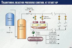
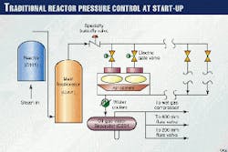
In the traditional control method, the operator puts a large amount of steam into the reactor to raise and control the reactor pressure (Fig. 1). The steam flow is throttled by a special large throttle valve, usually located before the inlet pipe of the main fractionator's top oil gas cooler system. This throttle is usually performed by a pneumatic butterfly valve or several motor-operated gate valves on the inlet to the air coolers.
From April 1995 to June 1999, Sinopec experimented with an improved method of controlling reactor pressure during start-up at its No. 2 FCCU at its Shijiazhuang refinery.
Sinopec used either nitrogen or high-pressure gas (dry gas) from the plant's high-pressure gas header instead of steam to fill the reactor. The gas was throttled by 600-mm and 200-mm diameter flare valves to control the reactor pressure.
After 4 years of practice and improvement, Sinopec recommends the new method for FCC start-ups. The new method has the following advantages over the traditional way:
- Improved stability and flexibility of reactor pressure control.
- Easier catalyst fluidization between reactor and regenerator.
- Stricter control of catalyst loss into the slurry circulation system.
- Reduced unit start-up time.
- Avoidance of purchase of large specialty throttle valve.
- Reduced energy during FCC start-up.
Background of No. 2 RFCCU
In 1983, Sinopec successfully started up China's first resid FCCU (RFCCU) in the Shijiazhuang refinery. Construction for the second RFCCU, No. 2 RFCCU, began in 1993 and was completed in 1995. The Beijing Design Institute (BDI) designed the No. 2 RFCCU.
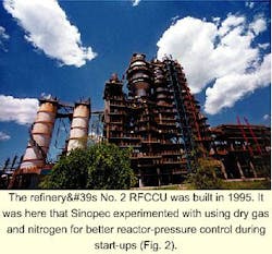
Fig. 2 shows a photo of the No. 2 FCCU unit at the Shijiazhuang refinery.
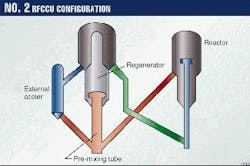
Fig. 3 shows the new FCCU regenerator design, which has a catalyst premixing tube and a down-flow catalyst cooler for high-efficiency regeneration.
BDI designed the No. 2 RFCCU for 800,000 tonnes/year of Daqing and Huabei atmospheric tower bottoms (ATB). Typical feed to the unit is a mix of unhydrotreated Huabei, Erlianhaote, and Xinjiang ATB.
The Conradson carbon residue content of the feed is generally 4-6 wt %. The nickel content is 15-23 ppm, and the vanadium content is 0.38-0.7 ppm. Total metals on the equilibrium catalyst amount to 10,000-14,000 ppm.
The company's operating philosophy is to maximize the unit's throughput in the gasoline and LPG mode. Maximum feed rates are 2,600-2,900 tonnes/day.
Traditional method
The main problem with the traditional way of controlling reactor pressure is large fluctuations in the pressure during control. The fluctuation is usually 25 kPa below or above the desired control value. If an unexpected situation occurs, the fluctuation could be worse.
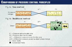
Traditional reactor-pressure control, however, uses a different principle. Because the maximum allowable working temperature of the air coolers is 130° C. and the maximum allowable inlet temperature of D201 is 50° C., air and water coolers are needed to run and condense steam into water (Fig. 4b).
Thus, the principle for this pressure control is P1=DP1+DP2+P2.DP2 is caused by the phase change when steam condenses into water; the value is influenced by the open-angle of the throttle valve, the steam amount, and the coolers' loading. These many variables result in large fluctuations of P1.In the traditional method, the solids content in the slurry usually exceeds the allowable concentration for stability. According to a primary calculation, a 10 kPa-reactor pressure fluctuation will cause a 3 or 4 m/sec surge in the inlet velocities of the reactor cyclones.
This surge brings about a large drop in cyclone efficiency. The fluctuation further causes a high amount of catalyst loss into main fractionator-bottoms system, which makes the normal slurry circulation more subject to interruption.
Finally, the traditional method requires a large amount of steam. To condense it, the air and water coolers must keep running. These additional utilities considerably increase energy costs at start-up.
Table 1 shows typical energy data using the traditional control method from the No. 1 RFCCU in the Shijiazhuang refinery.
The traditional method also requires an expensive throttle valve that is unnecessary with Sinopec's recommended method. The refinery typically uses the special throttle valve only for unit start-up, and the valve is generally useless during on stream operation; evidently, this is a waste. Besides this, such valve operation schedule is complicated, and maintenance costs are enormous.
An improved method
The key to solving the problems associated with the traditional method of reactor-pressure control is to use a continuous, simple, stable-phased material for the controlled system (Fig. 4a). This is safer and does not require a specially designed throttle valve.
This led the staff at the No. 2 RFCCU at Shijiazhuang refinery to develop a primary improved method for reactor pressure control during start-up.
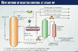
Fig. 5 shows the control configuration.
High-pressure gas, provided by the plant's high-pressure header, passes through C301, C303, LV305, through the rich diesel-return line to the main fractionator. It then comes into the fractionator where it joins with a small amount of steam from the reactor.
The stream then flows into the air and water coolers and D201. The operator controls this stream by throttling the 200-mm diameter flare valve (with help from the 600-mm diameter flare valve). The gas is then discharged into the low-pressure gas header for pressure control.
Specific operating advantages of using gas vs. steam include increased stability and safety, elimination of a valve, anti-interference ability, and a reduction in start-up time:
- Stability of gas phase. The high-pressure gas phase is always simple and stable. During an initial RFCCU start-up, there is no phase change for the high-pressure gas. The use of gas instead of steam solves the pressure-fluctuation problem caused by steam condensation.
- Safety of system operation. If air from the regenerator contacts the gas in the reactor, an explosion can occur. To avoid this, the new method secludes the reactor from the regenerator by closing the regenerated catalyst slide valve and the spent catalyst slide valve. Also, operators control the reactor pressure 10-20 kPa higher than that in the regenerator.
- Unnecessary specialty butterfly valve. Sinopec's new method for controlling reactor pressure uses the LV305 control valve to control the inlet amount of gas and the 200-mm and 600-mm diameter flare valves to control the pressure. Thus, the butterfly valve downstream of the main fractionator is unnecessary. Also, the motor-operated valves on the inlet to the air coolers are unnecessary.
- Anti-interference ability. Anti-interference is the ability to keep a system's pressure stable despite external influence. Compared with the traditional control method, the control system of the new method contains a larger volume.
The volume comprises the reabsorber tower (C303), air and water coolers, and oil, gas, and water separator (D201). This additional volume increases the whole system pressure capacity; so the new pressure control method's anti-interference ability is stronger.
- Reduction in start-up time. The new method reduces the amount of time needed to transition the unit from start-up to normal state.
In the traditional control method, after oil is sprayed into the riser, control takes two steps. In the first step, control is handled by the throttle valve then passed to the 600-mm and 200-mm diameter flare valves.
After the system is relatively stable and the wet-gas compressor is running without trouble, the flare valves transfer the control to the compressor speed controller.
The new method, however, does this all in one step, which reduces start-up time by several hours.
Application of new method
In April 1995, for the first time, the No. 2 FCCU at Shijiazhuang refinery attempted to start the unit using this nontraditional method of reactor control. Operating parameters from this start-up are shown in Table 2. The data in Table 2 indicated several improvements over the old method:
The stability of the reactor pressure control was largely increased. That is, the maximum pressure fluctuation during the whole process was less thanAs Sinopec continued to apply the new method during the next 2 years, it found two potential shortcomings.
First, in a unit emergency lay-off state, an undesirably long period was needed to draw the high-pressure gas from the gas header into the main fractionator.
Second, what if there was not enough plant high-pressure gas to accomplish the start-up in this manner?
For example, in May 1996, during a unit emergency shutdown, it took about 25-26 min to draw enough high-pressure gas to push the rich diesel oil in C303 through the return line into the main fractionator. This is dangerous, because the critical system pressure is out of control for that same period of time.
Not having enough high-pressure gas in the whole plant or having a pressure surge in the high-pressure gas system could cause problems when implementing the new method. This was a concern because when an FCCU starts up after a long downtime, the only thing provided by the high-pressure gas header is usually LPG, vaporized by a steam heater. It is obvious that vaporized LPG is not an ideal material for filling the reactor.
After considering various alternative start-up media, Sinopec selected nitrogen, a common and inexpensive gas. The refinery tied the nitrogen header to the main fractionator with a 50-mm diameter pipe.
In June 1999, while starting up the No. 2 FCCU after a long turnaround, Sinopec used nitrogen for the first time instead of the usual high-pressure dry gas to control the reactor's pressure during the initial start-up stage.
Key data comparing this start-up with those using steam and dry gas are shown in Table 3.
Not only did using nitrogen have the advantages of using dry gas instead of steam, it was more flexible and faster. A nitrogen flow of 8-10 kg/sq cm entered the main fractionator. The total time from normal pressure to the desired value was no more than 1-3 min, which meets any strict emergency requirement.
The Author
Zhang Tao is an executive director and process engineer for No. 2 RFCCU at Sinopec's Shijiazhuang refinery. He is responsible for No. 2 RFCCU's operation. Zhang has 9 years of refining experience. He holds a BS in chemical engineering from Hebei University of Technology, Tianjin City, China.
