Cost, lay method major factors in subsea coiled-tubing pipeline
Based on a presentation to the Offshore Tech nology Conference, Houston, May 3-6, 1999.
The experience of the Gulf of Suez Petroleum Co. (Gupco), Cairo, supports use of coiled tubing for certain subsea pipeline applications.
Gupco is a joint venture of Egyptian General Petroleum Corp. and BP Amoco.
Primary drivers for the company's using this technology were low cost and rapid installations. Although it considered or tried several installation methods, each provided an economic gain when compared to traditional methods.
The company has found that pipe diameter is the single most limiting factor in determining application feasibility. With advent of larger diameters, however, other limiting factors will likely include shipping, handling, and deployment.
Gupco installed its first 31/2-in. coiled-tubing pipeline in 1994. Subsequently, in 1996, it installed the first 41/2-in. coiled pipe high-pressure water supply line, which set a distance record of 62,000 ft (11.75 miles).
Since 1994, Gupco has installed approximately 250,000 ft (more than 47 miles) of coiled-tubing submarine pipelines for different applications.
Development; fabrication
While the history of reeled steel pipe can be traced to applications during World War II, coiled tubing has been used in the oil and gas industry primarily in well-servicing work. Dating from the mid-1960s, progressive developments in material capability and field-handling equipment have resulted in significant growth for the downhole coiled-tubing industry.
As late as 1990, the largest coiled tubing available was on 1.75 in. OD (44.5 mm). Since then, coiled-tubing manufacturers have continued to push the available size range to 4.5 in. OD (114.3 mm) with a maximum nominal 0.300 in. (7.62 mm) WT. This expanded range of diameter and wall thickness is one of the primary developments that makes possible application of continuously milled, reeled pipelines.
The manufacturing of coiled-tubing pipelines takes place in three steps:
- Assembly of steel strip required for the reel of tube.
- Production of the reel of tube from the assembled steel strip.
- Application of the external corrosion coating.
The raw material used in production of coiled tubing for pipeline applications consists of high strength, low-alloy carbon steel that is continuously cast and hot rolled to the final required thickness. Various grades of material are available with final product characteristics ranging from the equivalent of API 5L X-52 through an X-80 equivalent.
Because of various manufacturing and handling limitations, the lengths of the steel strips, as delivered to the tube manufacturers, are typically 1,000-3,000 ft (305-915 m), depending upon the gauge of the steel. Manufacturing a continuous reel of coiled tubing, therefore, requires accumulation of the entire quantity of strip material required for that reel in one continuous length.
Using a large, vertical collection reel, the coiled-tubing manufacturer will progressively weld several strips of raw material as required for the length of coiled tubing. The strip-joining welds will be X-ray inspected, heat treated, dimensionally finished, hardness tested, and dimensionally checked to ensure the highest quality. This process will be continued until all of the required strip material is accumulated into a single length.
The manufacturing of the finished product will see the strip material progressively formed into a tube in a series of rolls followed by creation of a longitudinal seam weld that uses a high-frequency induction welding process. This process creates a longitudinal weld capable of withstanding hundreds of reeling cycles while seeing plastic strain on each reeling cycle.
Following the creation of the longitudinal weld, the weld seam and heat affected zone are reheated to anneal this area. Following a continuous electromagnetic inspection of the weld seam for defects, the tube undergoes a final sizing operation and a stress-relief heat treatment before being neatly coiled at the end of the production line.
Testing; transportation
A series of tests on the finished tube ensures conformity with the required standards. The following tests are performed on specimens taken from the front end and back end of each reel of tube produced:
- Longitudinal tensile test: providing yield strength, tensile strength, and elongation.
- Metallographic examination.
- Microhardness testing: testing in weld fusion line, heat-affected zone, and base metal.
- Flare test.
- Flattening test.
- Hydrostatic test.
The third and final stage of the manufacturing operation involves application of the external corrosion coating.
The finished reel of coiled tubing is unspooled, passed through the coating line where it is prepared and the coating applied, then respooled following the necessary inspection of the finished product.
Different coating systems are available on the market and range in capability from a simple two-layer mastic-polyethylene system to a three-layer system consisting of fusion-bonded epoxy (one layer) and extruded polyethylene (two layer). This three-layer system is the most advanced coating system in the pipeline industry and provides exceptional performance with regard to corrosion protection and adhesion.
The material and the method used in the tube manufacturing yield several advantages when compared to conventional line pipe, including:
- Continuous lengths up to 23,000 ft (7,000 m) are possible, depending upon the diameter and wall thickness.
- The process used to manufacture the steel strip and the finished tube provides a tube with very consistent wall thickness and concentricity.
- The surface finish of the tube is much smoother than for conventional line pipe that, combined with the lack of circumferential butt welds, results in lower pressure drops than would be typically predicted.
- The external corrosion coating is also continuous which means better protection for the pipe than if field welds were required every 39 ft (12 m).
The quantity of coiled tubing that can be manufactured in one continuous length is limited by the size and weight of the spool required to transport the finished product. Typically, coiled-tubing manufacturers will limit the total weight of a finished spool of tube to about 80,000 lb (36.3 tonnes) which is dictated by the capability of the spooling and handling equipment at the manufacturers' plants.
For the 4.5 in. (114.3 mm) OD x 0.250 in. (6.35 mm) WT coiled tubing, a spool size of 204 in. (5.18 m) OD has been selected which can hold an average of 4,000 ft (1,219 m) of finished product. This spool can be transported by road if required and, with a weight of about 70,000 lb, is lifted by cranes in most locations.
Custom-built spools can be provided in order to meet the requirements of any particular application. The spools are typically equipped with receptacle areas for the application of wood lagging which offers protection to the pipe during transit to location.
As the spools being used to manufacture the 4.5-in. OD coiled tubing have a diameter of 17 ft and typically weigh about 35 tonnes when filled with product, this spool size can be road transported, although care must be exercised in planning this transport. Offshore handling of these reels needs to be planned carefully to ensure sufficient crane capacity is available.
The spools for manufacturing the 65/8-in. OD coiled tubing will necessarily be larger, typically about 25 ft in diameter. These spools are too large to be land transported and thus will ensure that 65/8-in. coiled tubing will be used only for offshore coiled-tubing pipeline applications.
Coiled pipe in the Gulf of Suez
In the 1990s, Gupco was faced with maturing fields and limited potential growth. One area of potential growth, however, was in marginal field development. These marginal opportunities had been identified in the past but were passed over for more lucrative developments.
As a result of their smaller sizes, these fields do not usually require large service pipelines (that is, the smaller coiled-tubing pipe is often adequate for the design rates). The marginal nature required innovative approaches to maximize economic return for the primary shareholders. Conventional pipeline costs a minimum of $100/installed ft for material, protective coating, transportation, and offshore installation.
Gupco challenged this unit rate of conventional pipeline and has successfully laid almost 250,000 ft of coiled-tubing pipelines to date.
Lay methods
Gupco's case history for the installation of 13/4-in., 31/2-in., and 41/2-in. coiled-tubing pipelines covers different pipelay arrangements ranging from the simple supply boat combination to use of a hook-up barge then a dynamically positioned vessel.
Supply boat
Use of a supply boat to lay coiled-tubing pipeline employs a combination of supply tugboats. Gupco used this method to develop the subsea completion R-22 and to lay a gas-lift pipeline between two platforms.
Fig. 1 presents views of the procedure; following was the installation sequence:
- The coiled-tubing lay equipment is loaded onto a supply boat.
- A soft rope is inserted into the 8-in. J-tube.
- The 8-in. J-tube is installed onto the host platform to accommodate the coiled-tubing riser.
- The supply boat is moored 400 ft from the host platform.
- A soft rope is connected between the pull cable aboard the supply boat and the J-tube soft line.
- The coiled tubing is pulled to the host platform by a winch near-by the top of the J-tube.
- As the pull operation continues, the diving-support boat monitors the coiled tubing's entrance to the inlet of the J-tube at the seabed.
- As the coiled-tubing pull operation is completed and the tubing reaches the top of the J-tube at the host platform, the supply boat sails towards the target boat.
- The target is another supply boat moored at the subsea completion to receive the installation boat as it reaches its target and helps the installation boat moor quickly and safely without creating damaging stresses to the coiled-tubing pipeline hanging at its tail.
- The installation supply boat sails to the target boat at the slowest possible speed.
- The tug boat controls the movement of the installation supply boat and helps keep the installation boat aligned with the coiled-tubing pipeline and avoid kicking the line.
- Pay-out of the coiled tubing is a manual operation. The operator keeps monitoring the coiled-tubing pipeline as it departs the boat and must make sure that coiled-tubing pipeline is touching the stinger rollers.
- The installation boat slows as it nears the target boat.
- As the installation boat moors along the target boat, the pipeline is terminated by a flange and laid to the seabed. A flexible spool is then used to connect the pipeline to the subsea completion.
Supply-boat laying has several advantages.
It is cost effective because marine vessels are available in offshore oil fields at reasonable daily rates. It is also simple and fast.
Use of a supply boat has certain limitations, however.
To begin with, the operation is successful only where no reel changeout is required. The distance between the initiation point and target must be less than one reel load of coiled tubing.
Also, the supply boat must travel at such a relatively high speed (150 fpm) that installation hydraulic equipment may overheat. Moreover, laying with a supply boat is not recommended in high-current areas or where the installation scene does not permit the tugboat to control the movements of the supply boat.
Also, this is a weather-sensitive installation arrangement. Coiled-tubing installation that uses a workboat arrangement should only be made in 2-3 ft seas (maximum).
Small barge
Based on lessons learned during the supply-boat-based installations and a pipeline failure in a high-current, narrow passage installation, Gupco abandoned use of boat-based-equipment installation.
The company decided to mitigate the weather-impact risk by using an anchor barge to host the coiled-tubing installation equipment. The company decided to lay 34,000 ft of 31/2-in. coiled tubing with a small barge and studied two options:
1. Coiled-tubing pull method with an anchor-handling tug to pull the coiled tubing from the anchored barge (Fig. 2).
Sufficient flotation throughout the pull operation assisted pipeline suspension and avoided dragging it across the coral seabed that might have damaged the line's protective coating.
2. The anchor barge moves away on its anchors to deploy the coiled-tubing pipeline.
With either configuration, barge installation provides excellent work area for reel changeout, is suitable for long coiled-tubing pipeline installation, and is less weather-dependent. The method is adequate for installation in up to 25 knots wind speed.
But there are limitations to barge-based coiled-tubing laying.
The operation is slow. Barge anchor-handling speed and barge movements on its anchors are critical in installation in that barge-anchor handling controls the laying speed of the barge rather than the pipelaying operation that takes place on the barge deck.
Average lay speed is 7 fpm. This low productivity leads to high installation costs.
DSV installation
Gupco elected to use a dynamically positioned diving-support vessel (DSV) to install 41/2-in. coiled-tubing pipe. Such a vessel retains the advantages of both dynamic laying (supply boat) and the anchor-barge laying.
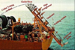
Lay equipment includes lay-ramp support, powered-reel support, coiled-tubing reel (laying position), coiled-tubing reels (storage), tensioner, and straightener.
The pipe was initiated over the gooseneck and through the straightener to the tensioner with use of a 10-tonne winch near the end of the lay-ramp support (Fig. 3).
Lay procedure, operation
Once loaded with the 14 reels of pipe (estimated capacity 4,300 ft/reel), the lay vessel sailed to the initiation site and was positioned at the riser.
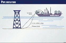
Divers installed a sheave block at the bottom of the platform pile. A winch line was passed from the cellar deck through the sheave block and to the vessel. Once received, the winch line was attached to the tubing-initiation head.
The winch then guided the pipe to the sheave block. Pipe was paid out through the tensioner at a predetermined tension to hold stress within allowable limits. The vessel moved forward to achieve the necessary catenary and continued until the entire pipe was paid out from the reel.
Fig. 4 presents a view of the beginning of pipelay.
At this point, the vessel stopped and held position. The line was secured in a hold back clamp behind the tensioner (forward of the straighteners). The empty reel was removed from the power reel support and replaced by a full reel.
Connections
The chosen method of connection involved use of "full bore" socket connections.
The socket is constructed of X-52 carbon steel with suitable weldability. It is preinstalled to the coiled tubing on the reel and inspected at the mill before shipment. This allowed a single weld and inspection to be performed for each reel.
This method of connection provides a conduit for pigging operations. Initiation was again achieved with the 10-tonne winch. The line was brought over the gooseneck, through the straightener to the holding clamp position. With a full-bore socket, the pipe was then readied for connection.
Mid-line connection is one of the crucial tasks of coiled-tubing pipeline installation; it is time consuming and remains in need of substantial improvements. On coiled-tubing pipeline projects, the frequency of mid-line connections has been every 4,000 ft, which was the average length of a coiled-tubing string.
The mid-line connection is made in five steps:
- Replacing the empty reel with a new one and bringing the new pipeline end down to the welding station.
- Welding, which is achieved by use of full-bore socket connector pre-welded to the new pipeline end. The aim of this tie-in technique is to minimize offshore welding time, the field weld being reduced to a single fillet weld.
- Weld inspection, which consists of magnetic particle inspection (MPI) on the fillet weld.
- Installation of a heat-shrink sleeve over the socket connector to allow continuity of the pipe's corrosion coating.
- Installation of a two-segment, bolt-on anode. As a reference, the connection time was 10-12 hr for the 1996 installations and was brought down to 6 hr on subsequent coiled-tubing projects.
Weld inspection was conducted with magnetic particle inspection.
Abandonment
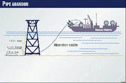
Upon reaching its target, the opposite platform, the vessel has passed as close as possible along the platform. As it passed over the abandonment point, the tubing was cut and an abandonment head was fitted to it with a pair of flanges.
The abandon cable was connected and the pipe abandoned as close as possible to its final location, with lateral movement of the vessel behind the platform to initiate a pipe shift (Fig. 5).
Once the pipe was on bottom, the abandon cable disconnected by divers, and parachutes and tirfors fastened to dead weights, the pipe shifted to its final location.
Weather
One of the main technical benefits of a coiled-tubing pipeline comes from its association with dynamically positioned (DP) vessels, which are best for coiled tubing in term of laying speed. Coiled tubing and a DP vessel form a near-perfect tandem for pipelay in medium to deepwater fields with a J-lay spread.
The ESMA field pipeline, for example, has been installed in the Gulf of Suez in a rough weather window with winds greater than 40 knots. Operating with a DP vessel and a modular layspread allowed the ramp to be set up to minimize the impact of the prevailing wind.
The ramp was set portside to generate a sideways lay, and the chance of installation was then increased from 10% for a standard stern lay position to 68%.
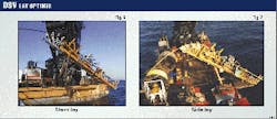
Figs. 6 and 7 present two examples of coiled-tubing lay configurations from the same DP vessel and lay spread: stern laying (Fig. 6) and sideways laying (Fig. 7) as implemented on the Esma project.
Illustrated are the flexibility and modularity of the lay equipment, which can be relocated easily, offshore, from stern to portside.
Dynamically positioned vessel installation has several advantages, including adequate travel speed, excellent stability for reel change out, pipeline initiation, and abandonment, and is generally not affected by weather.
Appraisal
Upon completing coiled-tubing pipeline installation, operator and supplier evaluated the performance of the offshore installations and developed the following recommended procedures for installations:
1. Use a remotely operated wire cutter during pipeline initiation.
The coiled-tubing lay was a relatively straightforward operation with no major problems. The lay was initiated with a 10-tonne air tugger to pull the pipeline off the lay ramp and reel and into a modified snatch block and latching arrangement, which was secured to the platform mudline brace or leg.
Locking of the initiation head into the latching mechanism was observed by use of a remotely operated vehicle (ROV). Thereafter, the initiation wire was slacked off and abandoned to the seabed for later recovery.
Initiation of the pipelay could be improved upon. This would require design of a remotely operated wire cutter that formed part of the return sheave and latching assembly. The initiation wire would be cut with the cutter once the pipeline had been pulled down and locked into the latching assembly. This would save upwards of 1.5 hr of vessel time on each initiation operation
2. Improve tension machine performance.
The lay ramp was equipped with a linear tracked winch unit, which was not sufficiently powerful to pull the 41/2-in. coiled tubing off the reel and through the straightener. The lay speed was limited to what was achievable with the catenary load to do what the linear tracked winch had been designed to do.
3. Avoid sharp turns.
Additional problems were encountered when the lay route had to accommodate bends or changes in direction. The touchdown point was kept as far from the vessel as possible in order to induce as much load in the catenary to assist in pulling the tubing off the reel and through the straightener.
This in turn made laying the line around bends very difficult because it had a tendency to skid across the seabed and pull straight.
4. Improve reel changeout process. Changing out of the coiled tubing reels was relatively simple. The alignment and welding operation to join the sections of lines was, however, very labor intensive and time consuming.
As this was a "first" for the project crew, it is worth noting that as the project progressed, the time taken to change out reels and complete the welding dropped from 8 to 4 hr. Of this time, approximately 1 hr was taken to clamp off the pipe on the lay ramp, cut it, and change out the reel.
The remaining time was spent on alignment, welding, wrapping an alignment device, and completing the joining of the reels at the powered reel drive unit and not on the lay ramp. It can be seen that the vessel spent most of the time in changing out reels and welding the lines together as opposed to laying.
Any means that reduces the number of connections required to perform on the vessel will increase the overall efficiency of the work spread. The changing out of reels was completed in the relatively calm waters of the Gulf of Suez.
Future operations in less favorable prevailing weather will require some control over the reels during changeout from the powered-reel drive unit.
Acknowledgments
The authors would like to thank the management of Gulf of Suez Petroleum Co., the Egyptian General Petroleum Co., and Amoco Egypt Oil Co. for their support.
The Authors
Farouk Kenawy is executive advisor to the Minister of Petroleum of Egypt. Formerly, he served as chairman of Gulf of Suez Petroleum Co. (1993-1998) and as chairman of Belayim Petroleum Co. Petrobel (1991-1993). He holds a BSc (1962) in petroleum engineering from Cairo University and a PhD (1970) from the Moscow Petroleum Institute. He is a member of SPE.
Wael F. Ellaithy is front-end loading manager for Gulf of Suez Petroleum Co., Cairo, and has served as project division manager. He holds a BSc (1976) in mechanical engineering from Alazhar University, Cairo. He is a member of SPE.


