Computer-assisted manufacturing (CAM), aided by a versatile workforce, information technologies, and efficient queue management, has reduced polycrystalline diamond compact (PDC) bit production times by more than 50% over the last 5 years.
As a result, oil and gas operators can now expect a shorter lead time in the manufacturing process, allowing them to redesign bits well after well while taking advantage of just-in-time delivery.
This conclusion of a two-part series (OGJ, Oct. 25, 1999, p. 57) provides exclusive details of the PDC manufacturing process along with insights into how a company-wide intranet has improved scheduling and production processes both locally and from plant to plant.
Powder vs. steel
A PDC bit consists of a crown, shank, and pin. The crown contains all the structural components necessary to drill the formation, while the shank and pin end connects to the bottomhole assembly.
Bit manufacturers make PDC bit crowns from solid steel or matrix powder. Each material has advantages that must be considered during the design-and-manufacturing process. For example, steel is easier to fabricate, making it a simple matter of milling the junk slots, blade shapes, cutter pockets, and fluid nozzles directly in the body of the bit.
"Although working with steel is less expensive than with matrix powder, steel is not as erosion resistant as matrix powder," said Roger Lee, drill bit engineer for Hughes Christensen. "Thus, if you're dealing with high rig costs, you want a bit that will stay in the hole a long time."
Yet with matrix powder, which is very tough and hard, "you can't mill." Instead, the bit manufacturer must use a procedure similar to a die-cast or plastic-injection molding process used in the toy and automobile industries.
Computer-assisted manufacturing
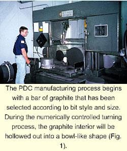
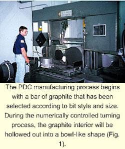
Thus, using the matrix-powder molding process, CAM begins with a bar of graphite (Fig. 1), chosen to fit the size and style of the bit.
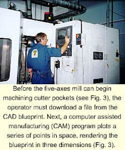
The graphite bar, which can only be used once, is mounted on a numerically controlled machine lathe where the interior is turned according to a 3D coordinate file downloaded from the computer assisted drafting (CAD) blueprint (see box: PDC manufacturing steps).
In essence, this numerical-control process, which ties CAD to CAM, produces a rough outline for the crown profile.
Pocket machining
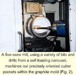
Once the basic bit profile is completely turned (see box: Manufacturing lingo), resulting in a hollowed out, bowl shape, the machine operator transfers and mounts the blank mold onto the chuck of a five-axes, numerically controlled mill (Fig. 2).
This automated milling machine, set up to load a series of bits and drills from a self-loading carousel, is used precisely to mill fluid-nozzle, PDC-cutter, and junk-slot pockets onto the mold, also according to the 3D coordinates provided by the CAD file (Fig. 3).
Therefore, although the matrix-powder manufacturing process does not involve milling bit features directly into the body of the bit, as it would with steel, it does require the operator to mill these same features, in reverse, onto the mold.
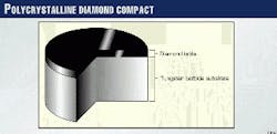
"To place the PDC cutters and nozzles later on in the process, we have to create spaces so we can eventually braze in the cutters and screw in the fluid nozzles," Lee said. "We can't set the cutters in the mold at this point because the furnace process will damage the bond between the diamond tables and tungsten-carbide backing (Fig. 4), so we have to braze them in afterwards."
Thus, mold preparation forms the most critical part of the process. "If the mold is incorrect, you will have a bad bit. Everything else afterwards can be modified or changed," he said.
Clay up mold
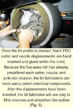
Once the junk slots, fluid nozzles, and PDC-cutter pockets are milled into place, the hollow mold is then moved to the plotting room where graphite cutter displacements (blanks) are hand set and glued into place (Fig. 5).
Although this step involves craftsmanship from skilled personnel, displacement positions are defined by the pocket and cavity orientations milled out in the prior step. "We simply cannot do this by hand without assistance from CAM," Lee said.
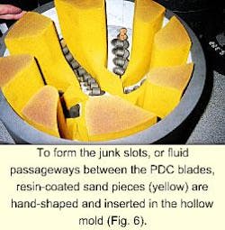
To produce the junk slots, or the fluid and cuttings pathways that reside between each blade, additional displacements made of resin-coated sand, graphite, and refractory clay are inserted (Fig. 6).
"What we do is give shape to the mold," said George Cortisse, bit fabricator for Hughes Christensen, "and it has to be smooth. We use graphite because it changes very little in the furnace. We also use sand because it holds it shape well."
Clay is used to make certain shapes that are difficult to form with sand while serving to fill in gaps that may produce problems in the clean-up process. "If we don't fill in these imperfections," Cortisse said," the binder will seep into every crack and crevice during the furnace process."
To finish the clay up mold step, nozzle displacements made of graphite are set in place along with a threaded receptacle that the driller will use to change out nozzle jets.
Powder fill
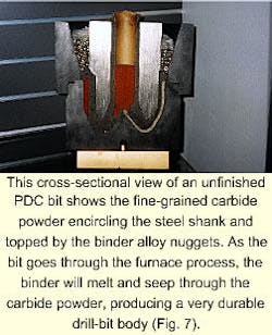
After the shape work in the plotting room is completed and inspected, the bit fabricators will then load the mold with a fine-grained tungsten carbide powder, insert a steel shank, top it off with a binder alloy, then preheat the assembly.
"Based on the application," said Bob Ausman, customer service manager of quality for Hughes Christensen, "we'll select the appropriate powder. For example if it has really deep junk slots and you need more strength in the blades, we'll select a powder with a higher density steel base.
"On the other hand, if the [oil company] operator expects a significant amount of solids or has poor solids control equipment, we'll select a more abrasion-resistant powder with a high concentration of tungsten carbide." Thus, powder composition depends on the wellbore environment, requiring input from the field before an optimum bit can be designed and manufactured.
It is also necessary to burn off (preheat) any organic material residing within the clay, resin, and sand parts before adding the binder and placing in the furnace. "If we put it directly into the furnace, its increased body heat would heat everything so fast that the gases would try to escape," Ausman said.
Additionally, because carbide powder does not melt during the furnace process, the binder, which serves as a glue that leaks down into the powder matrix, cements the carbide matrix in place.
This must be added between the preheat and furnace stages (Fig. 7). About a third to a half (by volume) binder, composed of copper-nickel alloy, is added to the powder along with a special flux additive.
"Once a mold has been loaded, say for an 81/2-in. bit, it will probably weigh 150 lb," Ausman said. And for a 171/2-in. bit, you're looking at 1,000 lb."
Furnace operation
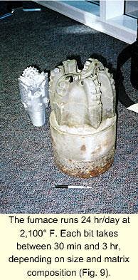
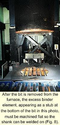
After the preheat treatment, the mold is placed into the furnace at 2,100° F. where it will remain 30 min to 3 hr, depending on bit size and style (Fig. 8). Afterwards, it is pulled over to a table, consisting of a table-mounted water spout, then cooled in a directed manner.
"Graphite is designed to take a thermal shock...it won't crack or split," Ausman said. However, "You want to keep the very top [of the bit] hot because that's where the binder is. If it's a perfect solidification, it will start slowly and work its way through the crown." In this way, the binder will continue to be liquid and be drawn down into the casting.
Otherwise, without the directed cooling action, the bit would cool in an almost homogeneous manner. Additionally, "If you don't draw the binder down into the matrix, you could compromise bit integrity by introducing voids into the matrix," he said.
Cleanup, crown work
Once the bit cools down and solidifies, the graphite mold is broken away, leaving the cast exposed (Fig. 9). The graphite displacements and nozzle cavities are then drilled out and chiseled away. "It's a difficult task because graphite is very strong," Ausman said.
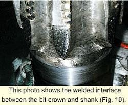
Next, the cast is sand blasted prior to the crown machine and brazing process. The binder head, appearing as an excess lump of material at the base of the crown (Fig. 9), must also be machined off and flattened to a smooth surface so that the drill shank can be attached and welded in place (Fig. 10).
"The shank assembly doesn't go through the furnace because the [prefabricated] API connection (pin end and threads), made of a high carbon alloy, must maintain certain material properties," Ausman said. "Otherwise, the furnace process will remove those properties."
Brazing and welding
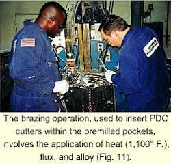
In preparation for the brazing operation, which consists of embedding individual PDC cutters within each of the preformed pockets, a preheat bath is used to remove contaminants or residues that could weaken the cutter-pocket bond.
Next, working closely together, the two-person operation, involving one individual who holds and spins the cutter while the other applies flux, alloy, and heat (1,100° F.), brazes each cutter in position by applying a thin layer of alloy between each cutter and pocket (Fig. 11).
"This is one of those processes you'd love to automate because it is extremely time consuming," Ausman said. However, the skill set required to do this work, which involves a high degree of training and experience, cannot at this time be replaced by a machine.
"Time and temperature are critical factors because if you bring it up too high, especially with the different material in the crown of the bit, the fill that's inside may crack at a different rate and fracture the crown," Ausman said.
Additionally, any flux inclusions or contaminants will affect the bond strength of the cutters.
Final cleanup, inspection
After the brazing process is completed, the bit is cooled and taken back to the cleanup room where the excess alloy, flux, and solder are removed with a diamond grinding wheel. Additionally, the gauge cutters, intentionally placed in excess of the drill bit's final OD, are ground back to the nominal bit diameter.
During this step, the bit fabricator uses an API ring gauge to verify tolerance specifications. Finally, the bit proceeds to the inspection stage where the bit fabricator conducts hardness and dye tests on the shank-crown weld along with ultrasonic testing of the PDC cutters.
Additionally, quality-insurance and bit-fabrication personnel conduct visual and dimensional inspections of the nozzle cavities and other bit components, double checking previous examinations conducted at each stage in the manufacturing process.
Finally, a numercially controlled, five-axes, coordinate measuring machine (CMM) serves to qualify cutter positions for the bits, molds, castings, and steel machined parts. The CMM can also be used to verify the accuracy of the numerically controlled machining equipment as well as verify shrinkage of different powders.
Process management
In addition to process improvements, imparted by developments in CAD and CAM technologies, product coordination, plant design, cross training, and information technologies inherently enhance work-flow efficiencies for the flexible manufacturing process.
Flexible workforce
"Almost every single day, our manufacturing flows have to be reorganized because some orders will be pushed ahead of others," said Roland Illerhaus, product manager of diamond products for Hughes Christensen.
For example, "An operator may be on location sooner than expected, or is drilling faster than anticipated, and needs the bit a day or two ahead of time. Thus, we have to shove it up front."
Cross training of the key manufacturing personnel has played a key role in the ability to reorganize the queue and switch from one bit to the next, on a moment's notice. "The main thing is flexibility of the work staff where they can change their tasks according to what is going on through the line," Ausman said.
"In the summer time, when things get tight, we may have 12 or 13 operations going on, instead of 2 or 3. Fortunately, most of our operatives are trained through half of it, as compared to only two or three functions in the past."
Thus, a truly flexible manufacturing system depends primarily on the skills and teamwork among plant personnel, and secondarily on the equipment side. "Our people pretty much manage themselves," Ausman said, "they pick their own team leaders and do their own housekeeping."
Queue management
Information technologies, implemented through a corporate-wide intranet, also provide huge gains for managing the flexible manufacturing system.
"From our Houston facility, we can actually see a bit progress through the shop in Germany-real time," said Randy Jackson, customer order coordinator for Hughes Christensen.
Basically, as each of the key manufacturing steps comes to a close, the operator walks over to a workstation and keys in information that records cycle time and qualifies pertinent information about the operation. "Once it is entered in the database, it automatically moves the bit to the next stage, tracking how much time it took, when it was completed, and when it'll be ready for the next operation," Jackson said.
This provides information that can be used in quantifying cycle-time metrics, scheduling, and resource management locally and, just as importantly, from plant to plant.
For example, "Not all of the facilities have the capability to make the graphite mold," Jackson said. "So Lafayette can say 'hey,' we need a mold and we can say 'no problem,' we'll schedule it in with our other orders. "Before the internet, with the manufacturing systems that are out there, we couldn't have done that."
Plant design
Plant design also plays an important role in reducing cycle time. "When we moved from Salt Lake City [5 years ago], we took advantage of the opportunity to redesign the whole [diamond] plant," Ausman said.
"In Salt Lake City, every bit sat on a cart and when you wanted to go from one operation to the next, you rolled that cart around. Basically, we had an inventory that was standing in place, resulting in a loss of visibility across the manufacturing process."
However, with an interconnecting network of continuous rollers (Fig. 8), proceeding from area to area, the physically continuous process of moving to the next step only serves to expedite the work process. "Plants that have been there for 20-30 years don't have that luxury," Ausman said.
Future benefits
The benefits of CAD and CAM, a flexible work force, information technologies, and an efficiently designed plant will only continue to shorten cycle times in the manufacturing process as new improvements are made along each step of the critical path.
In the past 5 years alone, production times for an 83/4-in. PDC bit have been reduced from 12 to fewer than 5 days.
Although some steps, like the time-and-temperature dependent furnace process, cannot be curtailed, almost every other step may achieve productivity gains through total quality management techniques and improvements in the automation process.
"You want to have the shortest possible lead time in manufacturing so you can supply the bit at the last minute," Illerhaus said. In fact, with the high costs for PDC bits, and the ability to customize drill bit architecture according to application, those operators that choose to use this technology will most certainly gain a competitive advantage by analyzing geologic information real time and ordering their bits as needed.
PDC manufacturing lingo
Language in the manufacturing process, like any other industry, uses specialized words to convey meaning:
Turning involves a process where the object to be worked on, mounted horizontally on a lathe, is shaped by a rotating device. In PDC manufacturing, this process is used to form the mold out of a bar of graphite.
Milling involves a stationary object that is acted upon by a cutting device (the opposite of turning). In PDC manufacturing, this process is used to mill the junk slots, PDC cutter, and fluid nozzle pockets.
Furnacing involves heating a loaded mold, consisting of a carbide powder topped with a binder alloy. Once the binder melts, it will infiltrate through the carbide powder and produce a durable bit body.
Brazing involves soldering a nonferrous metal that melts at a lower temperature than that of the metals being joined. During the brazing process, the braze serves as the glue that binds the PDC cutters to the cutter pockets.
Welding unites metallic parts, of different origin, by heating and allowing the metals to flow together. This process, which is used to join the pin shank and bit crown together in the PDC manufacturing process, changes the material properties of both parts at the interface.
Displacement refers to an object that is substituted within a preformed pocket to preserve shape and orientation. Because certain materials may be destroyed in the furnace, including PDC cutters, it becomes necessary to use displacements in the PDC manufacturing process.
Flux is a material used to remove oxides that build up on the braze surface during heating. If oxides remain on the braze surface, the braze alloy will not bond the cutter to the pocket.
Alloy, or solder, is the material used during the brazing process that welds or bonds the cutter to the cast matrix body.
