Test proves out triple-action pump in downhole separation
A new system has been tested for separating oil and water downhole in the wellbore.
Texaco's test of the triple-action pumping system (TAPS) included several breakthroughs that will push gravity-segregation technology towards widespread industry and government acceptance.
The test indicated that by virtue of its capability to inject at high pressure, TAPS provides a new, less-costly, method for waterflooding.
DOWS
Downhole oil-water separation (DOWS) is becoming a key technology in the oil industry. A number of published articles have discussed the potential of DOWS to improve revenues, reduce expenses and investments, and protect the environment when the right conditions exist.1-3
TAPS is capable of economically separating and injecting water downhole while producing only a fraction of the water to surface with the hydrocarbons. TAPS has extended the applicability of DOWS to "hard-rock country" where high injection pressures are common. TAPS, which has patents pending, may have accomplished the following industry firsts:
- It showed that oil and water segregation occurs even when the pump is placed below a well's producing perforations. This is significant when it is important to minimize backpressure on a well.
- It employed produced-water recycling to achieve environmentally friendly "zero discharge." That is, any water produced to surface was dumped back down the annulus and injected so that no water hauling was necessary. This process is a closed system that reduces discharge opportunities and facilitates chemical treating.
- A pseudo-permeability log, created from neural networks, was employed to select the optimum injection interval for a DOWS application.4
- A water-soluble, oil-dispersible chemical was used to protect both the producing and injection zones. This treating method appears to be far more successful than previous approaches.
Triple-action pump
TAPS improves on the design of the dual-action pumping system (DAPS).1-3 DAPS separates oil and water in the wellbore, lifting oil and some water while injecting the remaining water. TAPS performs these same two functions and provides at least three additional benefits.
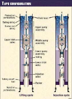
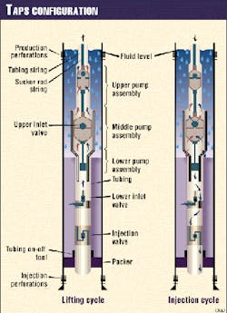
First, it provides a third action for magnifying injection pressure (Fig. 1). Similar to the concept of the pressure exerted by the heel of a spike-heeled shoe, TAPS transfers the force acting on a larger area to a smaller area to which it is directly connected. In this case, the force of the fluid column in the tubing acting on the large production plunger is transferred to the smaller injection plunger.
A second improvement of TAPS is that it is capable of operating in 4½-in. casing. The upper intake valve, which was mounted on the exterior of the tubing, was custom made for DAPS. In TAPS, a simple ported collar allows fluid to enter the pump.
TAPS is constructed of off-the-shelf equipment, so that a third benefit is its few specialty parts. The lower valve assembly, which is the intake for the injected water, is one of the specialty part.
TAPS is a relatively simple and inexpensive DOWS system, employing gravity segregation in the wellbore to separate produced fluids. This test showed that TAPS installations can be made without increasing operational loads on the pumping unit, motor, or rod string.
In fact, TAPS substantially reduced the load on the pumping unit's gear reducer while providing additional DOWS function.
Government role
At the time that TAPS was being designed, Argonne National Laboratory sponsored a program to provide U.S. Department of Energy (DOE) cost-sharing grants to test DOWS.
Argonne, which has been active in publicizing and supporting DOWS development, has proven to be very flexible and supportive.5 6 The supplemental funding not only allowed the development team to perform tests that would otherwise not have been conducted, but it also offset the costs of failures.
Obtaining permits can be one of the main hurdles for testing DOWS. Some projects die because of this proverbial pocket veto. But the New Mexico Oil Conservation Division proved to be very flexible because it quickly grasped the potential benefits of this test. A conventional underground-injection-control permit with some special provisions, such as access to the data, was granted on a temporary basis for the tests.
Candidate selection
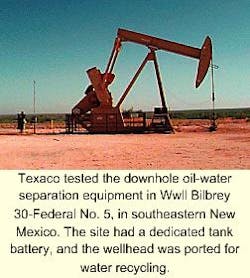
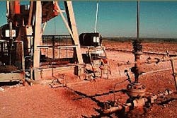
Another challenge of testing new technology is locating operators willing to risk a "good well." An ideal candidate proved to be Well Bilbrey 30-Federal No. 5, in the Lost Tank Delaware field, Lea County, N.M. (Fig. 2). The well was relatively new, so that the casing could handle injection pressure, a frequent problem with old wellbores that have been used often in previous DOWS tests.
The well had been completed in deeper zones that were uneconomic to produce. The rods and pumping unit, therefore, were oversized for the TAPS test, which would produce from a shallower zone. The well had the additional benefit of having dedicated tanks, a pump-off controller, no partners, and a significant economic incentive.
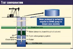
Fig. 3 displays the well configuration with the producing zone at 4,780 ft and the injection zone at 5,100 ft. The well was uneconomic at the time it was selected as a candidate, producing 17 bo/d and 190 bw/d. All produced water had to be hauled off by trucks for commercial water disposal, at significant cost.
Most critical, however, was the existence of a field-management team, from operation technician to operating unit manager, committed and willing to invest time, effort, and money in this technology.
A disposal zone was identified after the candidate well was selected. The original plan was to inject water into one of the deeper, uneconomic reservoirs that had already been stimulated.
Texaco's geologists, however, provided a unique solution that appears to be an industry first. They developed a pseudo-permeability log using a Texaco-patented process that employs neural networks to learn from existing log and core data.4
This pseudo-log showed that a far more permeable and thicker salt-water aquifer was just a few hundred feet beneath the producing zone. Completion of this interval proved less expensive and provided a reservoir that is undoubtedly more capable of absorbing injection water than other zones in the well.
TAPS design
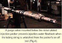
TAPS consists of a series of three sucker-rod pumps that actuate injection and production cycles. An injection packer between the production and disposal zones serves as a tubing anchor and as a boundary between the two cycles. A purge valve mounted below the packer prevents injection water flowback when the tubing string is unlatched from the packer's on-off tool (Fig. 4).
The lower valve assembly is a combination of valves that allows produced water to be loaded into the injection cycle from the casing-tubing annulus on the upstroke and displaced into the disposal zone on the downstroke.
A polished rod, stroking through a 3-ft pump barrel, hydraulically opens and closes the lower valve assembly to load and displace the injection cycle with produced water, as its working fluid. A sucker rod connects the injection cycle's polished rod to the production cycle. Two pumps of different sizes, one tubing pump and one insert pump, lift produced fluid to the surface.
Because TAPS cannot use a standing valve to load itself, two traveling assemblies were sized to create, on the downstroke, differential pressure in the cavity between them. This differential pressure opens the traveling valve in the larger, lower plunger, and loads TAPS during the production cycle.
On the upstroke, the cavity volume between the two traveling assemblies decreases, opening the traveling valve on the smaller, upper plunger, and allowing produced fluid to enter the tubing string. The amount of fluid produced to surface depends on the change in cavity volume between the two traveling assemblies.
A ported collar between the lower traveling assembly and the polished rod allows oil and some produced water to enter the production cycle. Balancing the size of TAPS' three sucker-rod pumps is critical to installation procedures for achieving the desired water injection volumes, overcoming required injection pressure, and producing sufficient oil volume to surface.
Having oversized equipment simplified the design process. Although the design enabled the pumping unit to do more work by moving more fluid than before, TAPS reduced the load range on the unit and rods. This load reduction occurs because the rod string and the injection interval continue to carry the fluid load on the downstoke. A conventional pump drops the fluid load onto the standing valve, which is supported by the tubing.
New Mexico permits surface-injection pressures up to 0.2 psi/ft in disposal wells without well testing. Texaco estimated and tracked the well's injection pressure by converting the well's minimum polished-rod load to an equivalent surface injection pressure.
The test well's disposal zone accepted water at 1,600 psig at the perforations or an equivalent surface injection pressure of less than 0 psi. The theoretical injection pressure limit on this installation is 0.65 psi/ft due to the pressure magnification effect of transferring hydraulic force on a large plunger to a smaller plunger.
Water recycling
A gravity-segregation DOWS typically brings about one-fourth or more of the total produced fluids to surface. One of the test's most aggressive goals was completely to eliminate water hauling by recycling produced water down the well's annulus. The lease's high water handling costs made it attractive to add this feature.
A plan was established to pull the produced water off the bottom of the production tank and let it siphon down the annulus. Primary concerns were:
- Breakdown of the fluid segregation process.
- Corrosion and scale effects.
- Additional withdrawal and injection capacity required.
- Mechanics for controlling the recycled water.
- Accurate determination of injection data.
Howard McKinzie of Texaco's technology division concluded that the water traveling down the casing-tubing annulus would immediately find the low side of the casing and stream down the side of the pipe. Whether it channels through the oil column or disperses is unresolved, but the end result is that produced water recycling worked.
Corrosion had been a particularly aggravating problem in DAPS installations. Some installations when pulled were completely corroded below the production cycle.
Unichem International, Hobbs, N.M., devised a corrosion solution that consisted of an oil-dispersible, water-soluble chemical that was added to the water-recycling stream. This has provided totally satisfactory protection, whereas the previous weighted chemical approaches often failed within a few months.
It now seems that weighted chemical simply does not have enough time to pass through the oil column; even though the units were turned off for as much as half a day.
Additional withdrawal and injection capacity was required to handle recycled water. Siphoning water down the well's casing-tubing annulus for injection was like taking four steps forward and one step back. The pump's production cycle might produce a given barrel of water more than once before that barrel of water was disposed of.
TAPS was designed to inject more fluid than it produced. This enabled the injection cycle to outrun the production cycle and pump the well off. Lengthening the stroke of the pumping unit was one way to increase the pump's ability to move fluid.
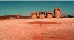
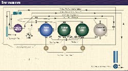
Control of the recycled water was established by a simple water-return system (Fig. 5). A heater-treater dump valve installed on the produced-water tank allowed water to enter the water-return line.
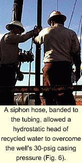
A Halliburton MC-II RTU water meter measured the amount of water recycled each day. From the meter, the water passed through a port in the wellhead and down the 90-ft x 3/8-in. siphon hose that was banded to the tubing (Fig. 6). The siphon hose was designed to use the hydrostatic head of the recycled water to overcome the well's 30-psig casing pressure.
Accurate injection volume determination depended upon accurate downhole stroke data. Industry-accepted calculations were used to estimate the pump's downhole stroke and injected water volume from a surface dynamometer, measuring forces acting on the polished rod.
Future testing will provide a verification of these calculations as they apply to TAPS. Injection-pressure data were gathered in a similar manner.
TAPS performance
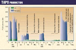
Fig. 7 provides a detailed rate-time curve. Management allowed installation of TAPS with a plan of working up to maximum capacity over a period of time, rather than immediately testing the ultimate capacity of the system. This process was beneficial in resolving problems such as an initial assembly configuration that had trapped gas within the injection-pump assembly.
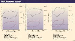
Trapped gas below the injection polished rod was partially responsible for the loss of about 50% of the injection cycle and can be observed at the beginning of the downstroke in the downhole pump card displayed in Fig. 8a.
An increase of 25% in the effective injection stroke was realized by modifying TAPS to better handle gas interference (Fig. 8b). Note the small load range of the card indicates that the life of the pumping unit and rods would be longer.
No mechanical problem with either the pump assembly or the rods was expected because the rod loading was less than 50% of rated capacity.
The concerns that setting the pump below the well's producing perforations could create separation problems proved unfounded. The ability to set the pump below the producing formation becomes important when an operator wants to minimize backpressure on that formation.
Well failures
Two preventable system failures occurred during the testing.
The first failure became apparent when oil production suddenly fell to zero.
The pump was pulled and inspected. It appeared to be in good condition, but there were indications of rod wear and the lower valve assembly had split.
A replacement lower valve assembly was installed and improvements were made to the injection cycle to reduce trapped-gas interference. Several sinker bars were installed to reduce the likelihood of a rod wear-related failure.
The increased pump efficiency was expected to help lower the fluid level of the well further, as the test continued to push towards obtaining the maximum withdrawal rate. The pump efficiency increased, but within a few weeks, the replacement lower valve assembly parted in precisely the same location as the previous failure.
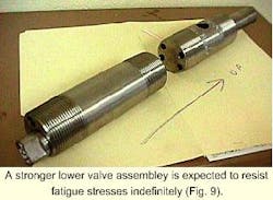
After the second failure of the lower valve assembly, it was realized that the injection pressure generated by TAPS was causing significant fatigue stresses in the lower valve assembly. Fatigue stress calculations showed that the lower valve assembly was loaded to 160% of maximum capacity.
A more robust lower valve assembly has been installed and is expected to resist fatigue stresses indefinitely (Fig. 9).
Data acquisition
Argonne's funding made it practical to acquire abundant data-adding to the scientific value of this test. Daily production and water recycling volumes as well as frequent dynamometer and fluid level measurements were recorded.
Additionally, Nabla Corp., Midland, Tex., provided a base-line dynamometer analysis as well as interpretation of unconventional TAPS data. These relationships proved to be helpful when it became evident just how difficult the data interpretation would be.
Vision
Texaco's testing and development of the triple-action pumping system was successful. Several breakthroughs were accomplished by this testing that will push gravity segregation technology towards widespread industry and government acceptance.
Gravity-segregation DOWS is on the low end of the spectrum for both production rate and cost, so that these technologies may prove valuable in the more mature oil producing basins. Almost without fail, tests of DOWS pumps have led to unforeseen benefits. This test was no exception.
A solution developed for the problem of trapped gas below TAPS has been successfully transferred to typical sucker-rod pumps to reduce gas interference conditions where high-compression valve cages and gas anchors had not provided relief.
A method for determining pumped-off conditions in a DOWS environment has been successfully tested. Less than complete loading of the TAPS production cycle is noticed at the beginning of the upstroke (Fig. 8c).
Also developed was a "siphon" method for reintroduction of produced water and facilitation of continuous chemical treatment.
Continued testing of TAPS to demonstrate its economic viability and reliability is planned. Additional testing is being arranged through Argonne National Laboratory because calculating downhole rate and injection pressure appears to be more complicated than originally anticipated.
Downhole rate and load sensors will be run to verify the calculated values so that the predictive model can be modified if necessary. Although developed for rod pump applications in mature, onshore settings, TAPS is a forerunner of downhole oil-water separation systems that may soon be used in high-cost applications to minimize hydrate or emulsion problems or to waterflood where it was previously unthinkable.
Acknowledgments
The authors gratefully acknowledge Texaco and Halliburton for permission to conduct and publish this test. We appreciate the support of John Veil of Argonne National Laboratory and the funding support of the US Department of Energy, National Petroleum Technology Office. Russell Pool, Homa Ray Short, and John Rogers of Texaco are acknowledged as critical management links. Jonathan Dimock of Halliburton Production Services and Ken Nolen of Nabla provided key analyses.
References
- Stuebinger, L., Bowlin, K., Wright, J., Poythress, M., and Watson, B., "Dual Injection and Lifting Systems: Rod Pumps," Paper No. SPE38790, SPE Annual Technical Conference and Exposition, San Antonio, Tex., Oct 5-8, 1997.
- Stuebinger, L., and Elphingstone, G., "Multipurpose Wells: Downhole Oil Water Separation in Your Future," Paper No. SPE49050, SPE Annual Technical Conference and Exposition, New Orleans, Sept. 28-30, 1998.
- Stuebinger, L., McKinzie, H., Elphingstone, G., and Gallaher, D., "Protecting Water Resources with DOWS," Annual Meeting of the Ground Water Protection Council, Sacramento, Calif., Sept 19-23, 1998.
- Wiener, J., Rogers, J., and Moll, B., "Predict permeability from wireline logs using neural networks," Petroleum Engineer International, Vol. 68, No. 5, 1995, p. 18-24.
- Veil, J., Langhus, B., and Belieu, S., "Feasibility Evaluation of Downhole Oil/Water Separator (DOWS) Technology," January 1999.
- Veil, J., Langhus, B., and Belieu, S., "DOWS Reduce Produced Water Disposal Costs," OGJ, Mar. 22, 1999, pp. 76-84.
The Authors
Jason Wacker is a production engineer for Texaco's Carlsbad field management team, Hobbs, N.M. He is a graduate of Texas Tech University, Lubbock.
Lon Stuebinger is an engineer for Texaco in Denver. He is the primary inventor of DAPS, TAPS, and other DOWS technologies. Stuebinger is a graduate of the Colorado School of Mines, Golden.
Robert M. Parker is a field technician for Texaco's Carlsbad field management team and is an expert at pumping well analysis. Parker is a graduate of Texas A&M University.
Ralph Harding is the reliability engineering coordinator for Texaco's Permian business unit, Midland, Tex. Harding holds a BS in petroleum engineering from Texas Tech University, Lubbock.
Brock Watson is a design engineer for Halliburton Production Services, Carrollton, Tex.
